2 programming mode constants – Yaskawa VS-626 MC5 User Manual
Page 212
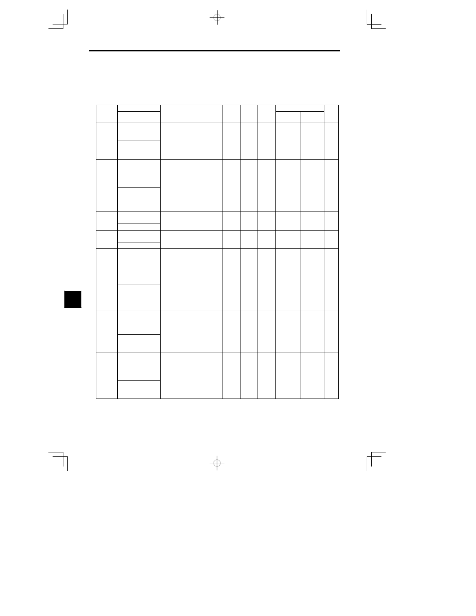
User Constants
8.2.1 Application Constants: b
- 4
8.2
Programming Mode Constants
8.2.1 Application Constants: b
J
Operation Mode Selections: b1
Constant
Name
Setting
Factory
Change
during
Control Methods
Constant
Number
Display
Description
Setting
Range
Factory
Setting
g
during
Opera-
tion
Open Loop
Vector
Flux Vector
Page
b1-01
Reference selection
Used to set the input method for the
frequency reference.
0: Digital Operator
1: Control circuit terminals (ana-
0 to 3
1
Q
Q
- 4
b1-01
Reference Source
1: Control circuit terminals (ana-
log inputs).
2: Transmission
3: Option Card
0 to 3
1
Q
Q
4
- 7
b1-02
Operation method
selection
Used to set the source of the run
command.
0: Digital Operator
1: Control circuit terminals (se-
quence inputs).
2: Transmission
0 to 5
1
Q
Q
- 9
b1 02
Run Source
2: Transmission
3: Option Card
4: MEMOBUS transmission (for
CP--717)
5: Winding change sequence
0 to 5
1
Q
Q
- 9
b1-03
Stopping method
selection
Used to set the stopping method
used when a stop command is in-
put
0
0
Q
Q
- 12
b1 03
Stopping Method
put.
0: Ramp to stop
0
0
Q
Q
- 12
b1-04
Prohibition of reverse
operation
0: Reverse enabled
0
0
B
B
- 11
b1 04
Reverse Oper
0: Reverse enabled
0
0
B
B
- 11
b1-05
Operation selection
for setting of E1-09 or
less
Used to set the method of operation
when the frequency reference input
is less than the minimum output
frequency (E1-09).
0: Run at frequency reference
(E1-09 not effective).
1: STOP (Frequencies below
E1-09 in the coast to stop state.)
0
3
0
A
- 25
Zero-Speed Oper
E1-09 in the coast to stop state.)
2: Run at min. frequency. (E1-09)
3: Run at zero speed (Frequencies
below E1-09 are zero)
This function is only available in
with flux vector control.
b1-06
Read sequence input
twice
Used to set the responsiveness of
the control inputs (forward/reverse
and multi-function inputs.)
0: Two scans every 2 ms (Use
when connecting transistor out-
)
0 1
1
A
A
- 9
b1 06
Cntl Input Scans
when connecting transistor out
puts.)
1: Two scans every 5 ms (Use
when connecting contact out-
puts or switches.)
0 1
1
A
A
- 9
b1-07
Operation selection
after switching to re-
mote mode
Used to set the Operation mode by
switching to the Remote mode us-
ing the Local/Remote Key.
0: Run signals that are input dur-
ing mode switching are disre-
garded. (Input Run signals after
0 1
0
A
A
- 9
LOC/REM RUN Sel
garded. (Input Run signals after
switching the mode.)
1: Run signals become effective
immediately after switching to
the Remote mode.
8