7 installing and wiring pg speed control cards – Yaskawa VS-626 MC5 User Manual
Page 57
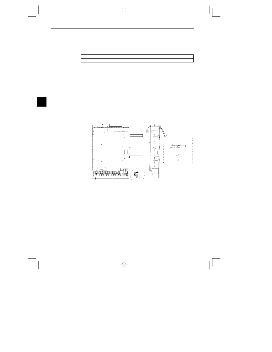
Wiring
3.7.1 Installing a PG Speed Control Card
- 24
3.7
Installing and Wiring PG Speed Control Cards
PG Speed Control Cards are used for executing speed control using a pulse generator (PG). There are four types
of PG speed control, as shown below. Select the type that fits the application and control method.
PG-B2
A/B-phase pulse input for open collector output or complementary outputs, for vector control
PG-X2
A/B/Z-phase pulse input for line driver input, for vector control
3.7.1 Installing a PG Speed Control Card
Use the following procedure to install a PG Speed Control Card.
1. Turn off the main-circuit power supply.
2. Leave it off for at least one minute before removing the front cover of the Inverter (or at least three
minutes for Inverters of 30 kW or more). Check to be sure that the CHARGE indicator is OFF.
3. Insert the spacer (which is provided) into the spacer hole in the Inverter’s mounting base.
For Inverters of 3.7 kW or lower, there are two adjacent holes. Insert the spacer into the 7CN hole. The
spacer cannot be easily removed if inserted into the wrong hole. Be very careful to insert the spacer
into the correct hole, and in the proper direction.
4. Referring to the enlarged illustration in the following diagram, align the PG Speed Control Card with
the catch position as shown by (a) and (b) and fit it precisely to the Option-A connector. Insert at (a)
first.
5. Pass the spacer through the spacer hole at the Card. (Refer to A in the illustration.) Check to be sure
that it is precisely aligned with the 4CN position, and snap it into the proper position. Be sure to press
it in firmly until you hear it snap into place.
Spacer mounting hole
Top
Option A
Option C
Control
board
Option D
4CN
Option-A
Connector
2CN
Option-C
Connector
3CN
Option-D
Connector
Connection
terminals
Ground terminal 12
Bottom
[Front]
Enlargement
Option A mounting spacer
(Accessory
:
SRNT41028-9)
Inverter mounting base
Inverter
mounting base
Spacer mounting
hole
Control board
Spacer
Mounting
base side
Option A side
Spacer mounting
Side
(
b
)
(
a
)
PG Speed Control Card
7CN
PG Speed
Control
Card
Fig
3.22
Installing a PG Speed Control Card
3