Yaskawa VS-626 MC5 User Manual
Page 184
Advanced Operation
7.3.5 External Terminal Functions: H
- 46
J
Multi-function Analog Output Settings: H4-01 to H4-07
Function Selection Constants: H4-01, H4-04
User
Change
during
Setting
Factory
Valid Access Levels
User
Constant
Number
Name
during
Opera-
tion
Setting
Range
Unit
Factory
Setting
Open Loop
Vector
Flux Vector
H4-01
Monitor selection (ter-
minal 21)
1 to 35
--
2
B
B
H4-04
Monitor selection (ter-
minal 23)
1 to 35
--
3
B
B
D
The multi-function outputs can be set to monitor any of the U1 Inverter status items by setting the last
two digits of the constant number (U1-jj).
Refer to page - 12 for a table listing all of these U1 settings.
D
Settings 4, 10, 11, 12, 13, 14, 25, 28 and 34 can’t be set and settings 29, 30, and 31 aren’t used.
Adjusting the Monitor Output: H4-02, -03, -05, -06
User
Change
during
Setting
Factory
Valid Access Levels
User
Constant
Number
Name
during
Opera-
tion
Setting
Range
Unit
Factory
Setting
Open Loop
Vector
Flux Vector
H4-02
Gain (terminal 21)
0.00 to 2.50
Mul-
tiple
1.00
B
B
H4-03
Bias (terminal 21)
--10.0 to
+10.0
%
0.0
B
B
H4-05
Gain (terminal 23)
0.00 to 2.50
Mul-
tiple
0.50
B
B
H4-06
Bias (terminal 23)
--10.0 to
+10.0
%
0.0
B
B
D
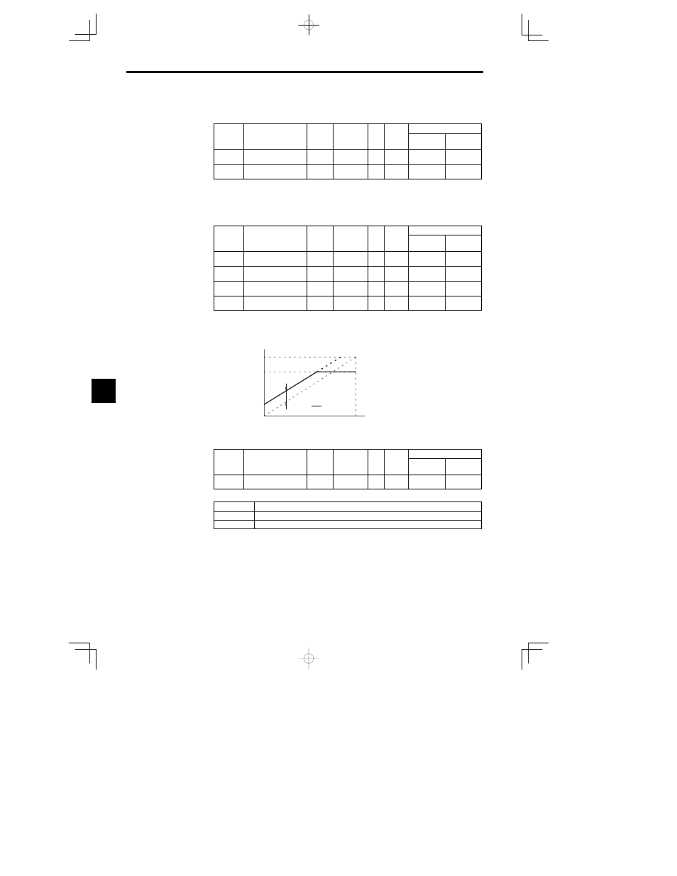
For the output gain, set what multiple of 10 V will correspond to a 100% output of the monitored item.
D
For the output bias, set the amount that the output characteristic will be shifted vertically.
Set this amount as a percentage, with 10 V corresponding to 100%.
Output voltage
Gain
u
10 V
10 V
0 V
Monitored item
0 %
100 %
Bias
u
100
10 V
Fig
7.28
Monitor Output Adjustments
Multi-function Analog Output Signal Level: H4-07
User
Change
during
Setting
Factory
Valid Access Levels
User
Constant
Number
Name
during
Opera-
tion
Setting
Range
Unit
Factory
Setting
Open Loop
Vector
Flux Vector
H4-07
Analog output signal
level selection
0 1
--
0
B
B
D
Settings
Setting
Function
0
0 to +10 V (Absolute value output)
1
0 to 10 V
D
This signal level setting applies to analog outputs 1 and 2 (terminals 21 and 23).
D
When the 0 to
r10 V signal level is used to output speed values (frequency reference, output frequency,
or motor speed), positive voltage indicates Inverter output in the forward direction and negative volt-
age indicates Inverter output in the reverse direction. (Assuming a bias setting of 0.0.)
D
There are some monitor items that are limited to the 0 to +10 V signal range even when the 0 to
r10 V
signal level has been selected. Refer to Table 4.3 Status Monitor Items for details.
J
MEMOBUS Communications Settings: H5-01 to H5-05
Station Node Address: H5-01
D
Set the Inverter node address.
7