1 protective and diagnostic functions, 1 fault detection – Yaskawa VS-626 MC5 User Manual
Page 246
Troubleshooting
9.1.1 Fault Detection
- 2
9.1
Protective and Diagnostic Functions
9.1.1 Fault Detection
When the Inverter detects a fault, the fault code is displayed on the Digital Operator, the fault contact output
operates, and the Inverter output is shut OFF causing the motor to coast to a stop. (The stopping method can
be selected for some faults, and the selected stopping method will be used with these faults.)
D
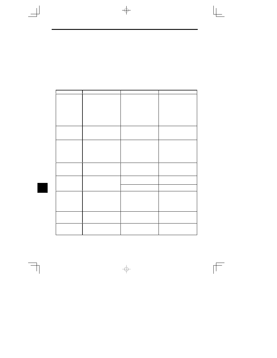
When a fault has occurred, refer to the following table to identify and correct the cause of the fault.
D
Use one of the following methods to reset the fault after restarting the Inverter:
x
Turn ON the fault reset signal.
(A multi-function input (H1-01 to H1-06) must be set to 14 (Fault Reset).)
x
Press the RESET Key on the Digital Operator.
x
Turn the main circuit power supply off and then on again.
Table
9.1
Fault Displays and Processing
Fault Display
Meaning
Probable Causes
Corrective Actions
OC
Overcurrent
Overcurrent
The Inverter output current exceeded
the overcurrent detection level.
(200% of rated current
S A short-circuit or ground fault oc-
curred at the Inverter output. (A
short or ground fault can be caused
by motor burn damage, worn in-
sulation, or a damaged cable.)
S The load is too large or the accelera-
tion/deceleration time is too short.
S A special-purpose motor or motor
with a capacity too large for the In-
verter is being used.
S A magnetic switch was switched at
the Inverter output.
Reset the fault after correcting its
cause.
GF
Ground Fault
Ground Fault
The ground fault current at the Invert-
er output exceeded approximately
50% of the Inverter rated output cur-
rent.
A ground fault occurred at the Invert-
er output.
(A ground fault can be caused by mo-
tor burn damage, worn insulation, or a
damaged cable.)
Reset the fault after correcting its
cause.
PUF
DC Bus Fuse Open
Fuse Blown
The fuse in the main circuit is blown.
The output transistor has failed be-
cause of a short-circuit or ground
fault at the Inverter output.
Check whether there is a short-circuit
between the following terminals. A
short-circuit will damage the output
transistor:
B1 (¨3)
l U, V, W
©
l U, V, W
Replace the Inverter after correcting
the cause.
SC
Short Circuit
Load Short-circuit
The Inverter output or load was short-
circuited.
A short-circuit or ground fault oc-
curred at the Inverter output. (A short
or ground fault can be caused by mo-
tor burn damage, worn insulation, or a
damaged cable.)
Reset the fault after correcting its
cause.
OV
Overvoltage
Main Circuit Overvoltage
The main circuit DC voltage exceed-
ed the overvoltage detection level.
The deceleration time is too short and
the regenerative energy from the mo-
tor is too large.
Increase the deceleration time or con-
nect a braking resistor (or Braking
Resistor Unit).
Overvoltage
ed the overvoltage detection level.
200 V class: Approx. 400 V
400 V class: Approx. 800 V
The power supply voltage is too high.
Decrease the voltage so it’s within
specifications.
UV1
DC Bus Undervolt
Main Circuit Undervoltage
The main circuit DC voltage is below
the undervoltage detection level
(L2-05).
200 V class: Approx. 190 V
400 V class: Approx. 380 V
S An open-phase occurred with the
input power supply.
S A momentary power loss occurred.
S The wiring terminals for the input
power supply are loose.
S The voltage fluctuations in the input
power supply are too large.
Reset the fault after correcting its
cause.
UV2
CTL PS Undervolt
Control Power Fault
The control power supply voltage
dropped.
-- --
S Try turning the power supply off
and on.
S Replace the Inverter if the fault con-
tinues to occur.
UV3
MC Answerback
Inrush Prevention Circuit Fault
A fault occurred in the inrush preven-
tion circuit.
-- --
S Try turning the power supply off
and on.
S Replace the Inverter if the fault con-
tinues to occur.
9