4 standard connection diagrams – Yaskawa VS-626 MC5 User Manual
Page 45
Wiring
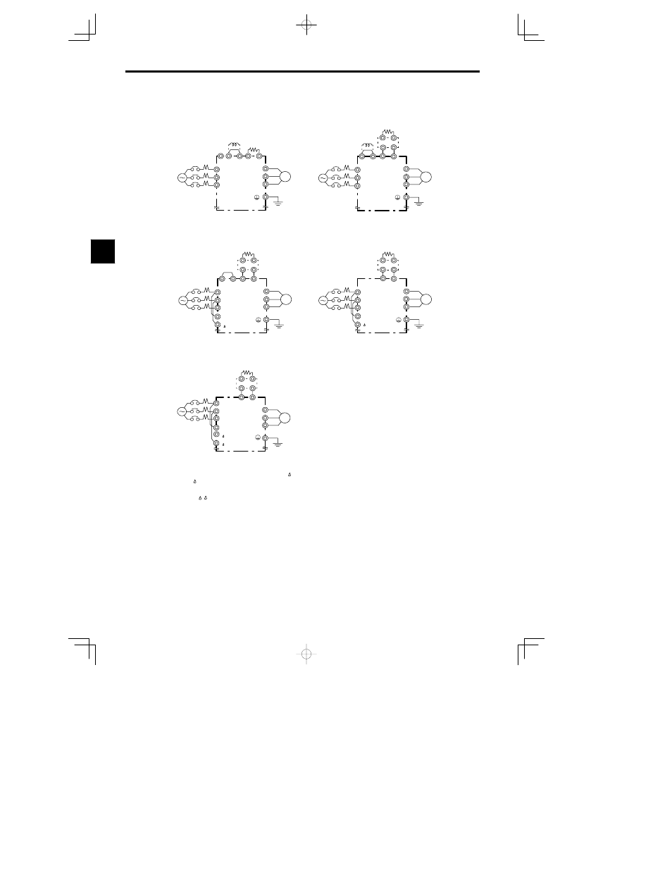
3.4.4 Standard Connection Diagrams
- 12
3.4.4 Standard Connection Diagrams
*
1 Input the control circuit power supply from r--
for 200 V class Inverters of 30 to 75 kW (2030 to 2075) and
from r- 400 for 400 V class Inverters of 55 to 75 kW (4055 to 4075). (For other models, the control power
supply is supplied internally from the main circuit DC power supply.)
*
2 The r--R, ( 400)-S terminals are short-circuited for shipping.
Remove the short wiring from the 2018, 2022,
4018 to 4045
when supplying power to the main circuits from the DC power supply.
CIMR-MC5A20P4 to 27P5, 40P4 to 4015
CIMR-MC5A2018, 2022, 4018 to 4045
CIMR-MC5A4055 to 4075
CIMR-MC5A2011, 2015
CIMR-MC5A2030 to 2075
DC reactor
(optional)
Braking Resistor
Unit (optional)
3-phase 200 VAC
(400 VAC)
Be sure to remove the short-circuit bar before
connecting a DC reactor.
DC reactor
(optional)
Braking Resistor
Unit (optional)
Braking Unit
(optional)
3-phase 200 VAC
Be sure to remove the short-circuit bar before
connecting a DC reactor.
The DC reactor is built in.
The DC reactor is built in.
3-phase 400 VAC
The DC reactor is built in.
© ¨
1
¨
2
B1
B2
R
S
T
U
V
W
IM
©
¨
1
¨
2
R
S
T
U
V
W
IM
¨
3
3-phase 200 VAC
(400 VAC)
Braking Resistor
Unit (optional)
Braking Unit
(optional)
©
¨
1
¨
2
R
S
T
U
V
W
IM
¨
3
r
*2
Braking Resistor
Unit (optional)
Braking Unit
(optional)
3-phase 200 VAC
R
S
T
U
V
W
IM
r
*1
*2
Braking Resistor
Unit (optional)
Braking Unit
(optional)
©
¨
3
©
R
S
T
U
V
W
IM
¨
3
r
*1
200
400 *2
Fig
3.6
Main Circuit Terminal Connections
3