Yaskawa VS-626 MC5 User Manual
Page 167
7.3
Common Functions
- 29
D
For the output monitor selections (F4-01, F4-03), set the numbers for the right side of the “U1”
constants in the Table 4.3. The setting range is 1 to 38, but the following numbers cannot be set: 4, 10,
11, 12, 13, 14, 25, and 28 to 35.
D
When the AO-12 is used, outputs of 0 to
r10 V are possible. For that, set constant H4-07 (multi-func-
tion analog output signal level selection) to “1” (0 to
r10 V outputs). There are some monitor items.
However, that can only use outputs of 0 to +10 V even if constant H4-07 is set to “1.”
D
When the AO-08 is used, only outputs of 0 to +10 V are possible regardless of the constant H4-07 set-
ting.
D
Set the amount of parallel movement by raising or lowering the output characteristics in the output
bias.
Use a percentage (%) as the unit of measurement with 10 V equalling 100%.
J
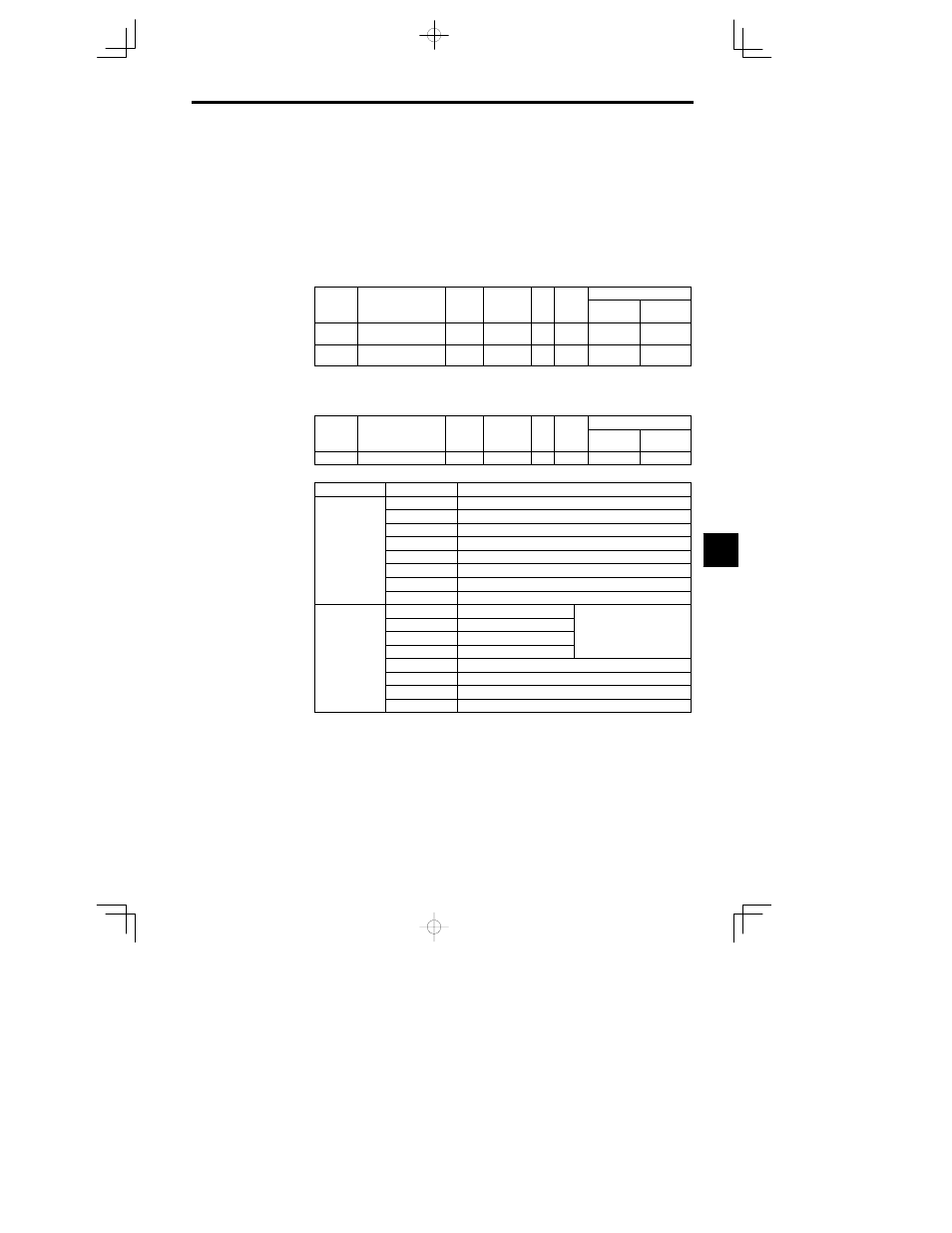
DO-02 Digital Output Card Settings: F5-01 F5-02
D
Set the output selections in the following constants when using a DO-02 Digital Output Card.
User
Change
during
Setting
Factory
Valid Access Levels
User
Constant
Number
Name
during
Opera-
tion
Setting
Range
Unit
Factory
Setting
Open Loop
Vector
Flux Vector
F5-01
Channel 1 output selec-
tion
00 to 37
--
0
B
B
F5-02
Channel 2 output selec-
tion
00 to 37
--
1
B
B
D
Set the values from Table 7.7.
J
DO-08 Digital Output Card Settings: F6-01
D
Set the output mode in the following constants when using a DO-08 Digital Output Card.
User
Change
during
Setting
Factory
Valid Access Levels
User
Constant
Number
Name
during
Opera-
tion
Setting
Range
Unit
Factory
Setting
Open Loop
Vector
Flux Vector
F6-01
Output mode selection
0 1
--
0
B
B
D
The items output from the DO-08 will be as follows according to the setting of F6-01.
Setting
Terminal
Output
TD5-TD11
Overcurrent SC OC GF
TD6-TD11
Overvoltage OV
TD7-TD11
Inverter overload OL2
0: 8 channels of
individual out
TD8-TD11
Fuse blown PUF
individual out-
puts
TD9-TD11
Overspeed OS
puts
TD10-TD11
Inverter overheat OH1 or motor overload OL1
TD1-TD2
Zero speed detection
TD3-TD4
Speed agree
TD5-TD11
Bit 0
TD6-TD11
Bit 1
Binary code (see below)
TD7-TD11
Bit 2
Binary code (see below)
1: Binary code
TD8-TD11
Bit 3
1: Binary code
output
TD9-TD11
Zero speed detection
TD10-TD11
Speed agree
TD1-TD2
Running
TD3-TD4
Minor fault
7