Yaskawa VS-626 MC5 User Manual
Page 165
7.3
Common Functions
- 27
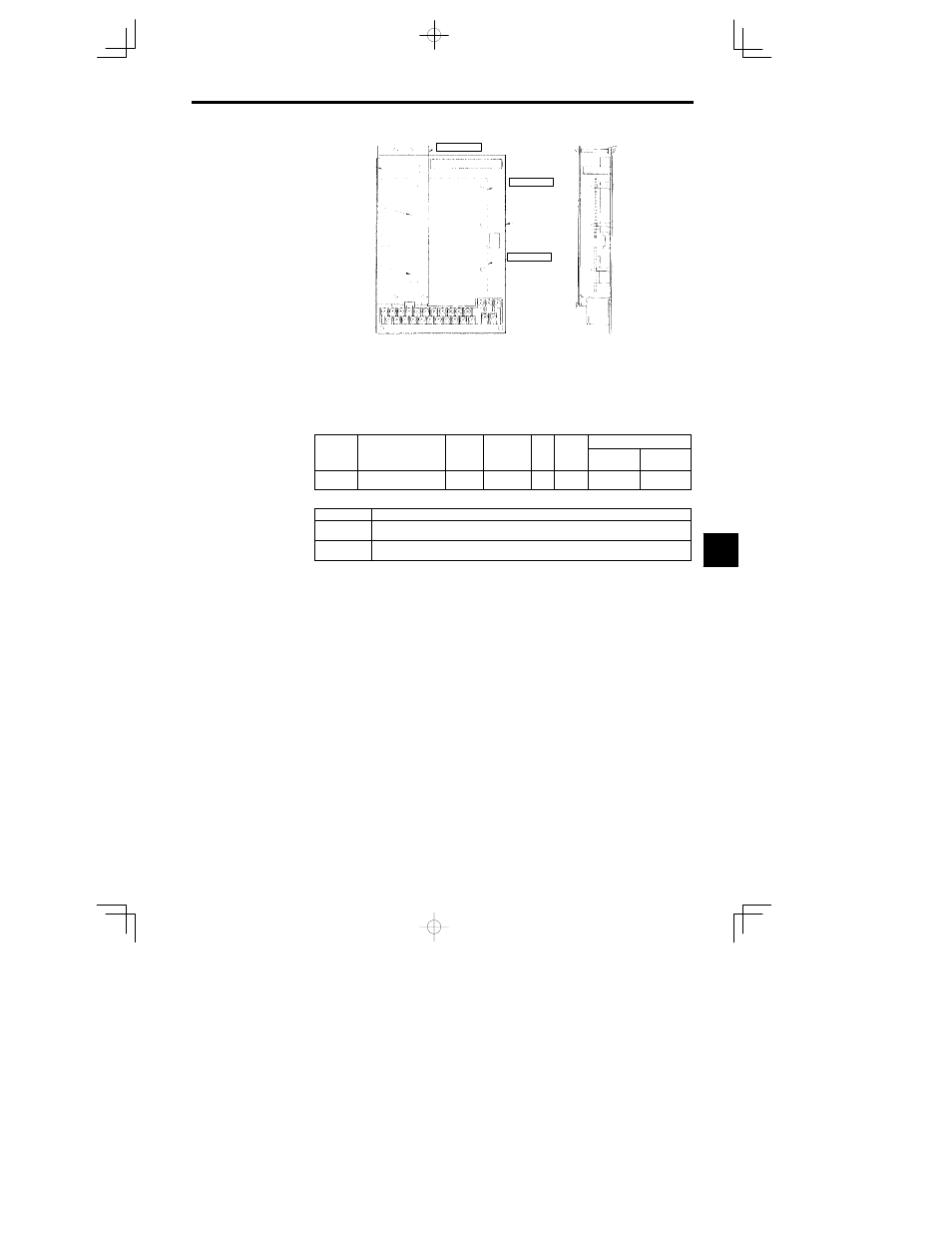
Option A
Option C
Control board
Option D
4CN
Option A con-
nector
2CN
Option C con-
nector
3CN
Option D con-
nector
Front View
Inverter
mounting base
Side View
7CN
Fig
7.15
Installation Locations for Option Cards
J
Analog Reference Card: F2-01
D
When using a AI-14B/A1-14U Analog Reference Card, set constant b1-01 (reference selection) to “3”
(option).
D
When using a AI-14B, set the function for channels 1 to 3 with constant F2-01. (There are no constants
to set for AI-14U.)
User
Change
during
Setting
Factory
Valid Access Levels
User
Constant
Number
Name
during
Opera-
tion
Setting
Range
Unit
Factory
Setting
Open Loop
Vector
Flux Vector
F2-01
Bi-polar or uni-polar in-
put selection
0 1
--
0
B
B
D
Settings
Setting
Description
0
3-channel individual input (CH1: terminal 13; CH2: terminal 14; CH3:
terminal 16)
b1-01 = 1
1
3-channel additional input (Sum of CH1 to CH3 is used as the frequen-
cy reference value.)
b1-01 = 3
D
Constant b1-01 (reference selection) must be set to “1” (external terminal), when 3-channel individual
input (setting: 0) is set.
D
When using a AI-14B and setting 3-channel individual input, the multi-function inputs cannot be set
to the Option/Inverter selection function (setting: 2).
7