Yaskawa VS-626 MC5 User Manual
Page 241
8.2
Programming Mode Constants
- 33
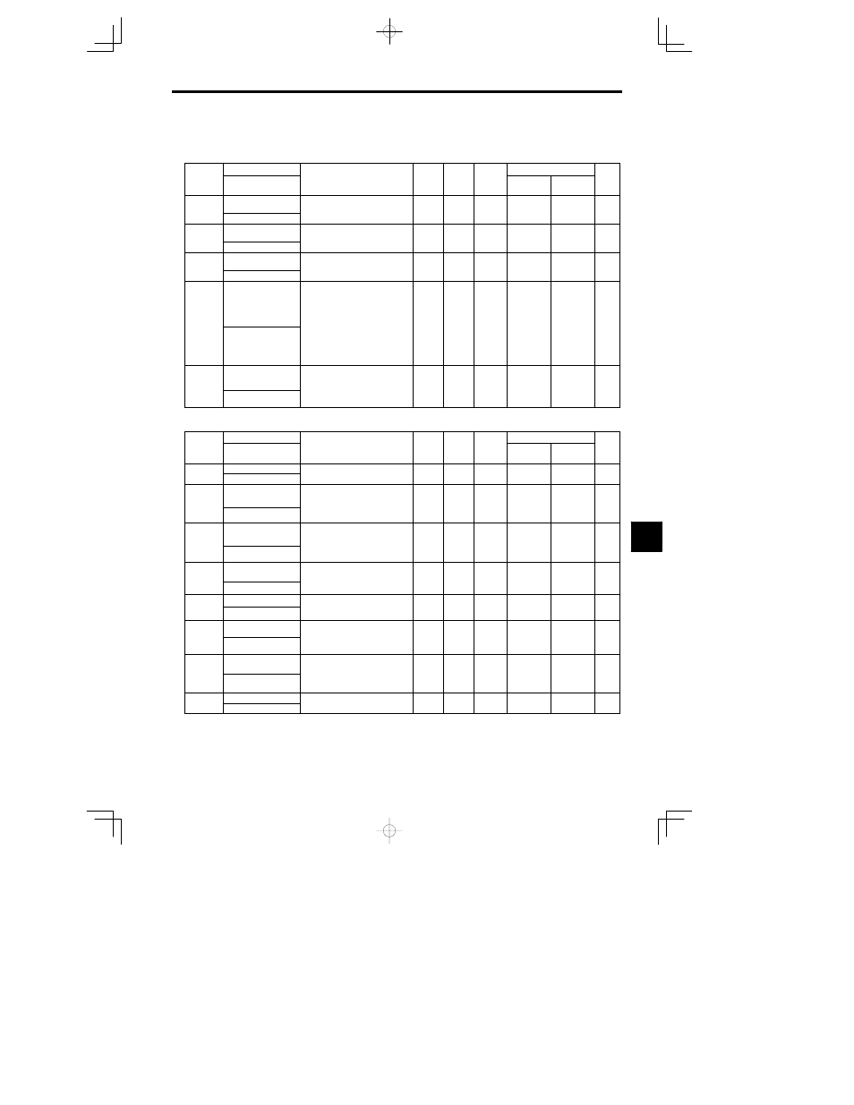
8.2.9 Winding Change Constants: P
J
Winding Change: P1
Constant
Name
Setting
Factory
Change
during
Control Methods
Constant
Number
Display
Description
Setting
Range
Factory
Setting
g
during
Opera-
tion
Open Loop
Vector
Flux Vector
Page
P1-01
Winding Change fre-
quency
Winding change frequency from Y-
winding and -winding
0.0 to
400 0
0.0
A
A
- 67
69
P1 01
Changeover freq
winding and -winding
400.0
0.0
A
A
- 69
P1-02
Winding change hys-
teresis
Winding change hysteresis
0.0 to
20 0
5.0
A
A
- 68
69
P1 02
Frequency Width
Winding change hysteresis
20. 0
5.0
A
A
- 69
P1-03
Answerback error de-
tectioon
Time setting of MC
answerback error detection
0.20 to
1 00
0.20
A
A
- 68
70
P1 03
Ansback Det Time
answerback error detection
1.00
0.20
A
A
- 70
P1-04
Motor constant selec-
tion
Constant setting for Y-winding
Selecting motor 1/motor 2
0: Motor 1 constants (E1, E2) are
used for Y-winding, and motor
2 constants (E3, E4, E5) are
used for
winding
0 1
1
A
A
- 66
- 68
P1 04
Wye Winding sel
used for -winding
1: Motor 2 constants (E3, E4, E5)
are used for Y-winding, and mo-
tor 2 constants (E1, E2) are used
for -winding
0 1
1
A
A
68
- 70
P1-05
Programming mode
valid/invalid during
run
MENU and ESC key
valid/invalid during run
0: Disabled
0 1
1
A
A
- 70
P1 05
Program Mode @
RUN
0: Disabled
1: Enabled
0 1
1
A
A
- 70
J
PG Orientation: P3
Constant
Name
Setting
Factory
Change
during
Control Methods
Constant
Number
Display
Description
Setting
Range
Factory
Setting
g
during
Opera-
tion
Open Loop
Vector
Flux Vector
Page
P3-01
Main Axis Zero Point
Sets the mechanical zero point of
h l
d
i
b
f
l
0 to
4095
0 pulses
No
B
B
P3-01
Position Origin
Sets the mechanical zero point of
the load axis as a number of pulses.
0 to
4095
0 pulses
No
B
B
----
P3-02
Position Control Gain
(H)
Sets the position control propor-
tional gain when a high-speed gear
is selected (MGR and LGR are
1 to 99
10
No
B
B
----
P3 02
Position Gain H
is selected (MGR and LGR are
OFF) or when high-speed winding
is selected (CHW is OFF).
1 to 99
10
No
B
B
P3-05
Positioning Comple-
tion Detection Width
Sets the detection width for output-
ting the completion signal as a
number of pulses when the load
1 to 99
5 pulses
No
B
B
----
P3 05
ORE Set Pulse
number of pulses when the load
axis approaches the command stop
position.
1 to 99
5 pulses
No
B
B
P3-06
Positioning Comple-
tion Cancel Width
Sets the positioning completion
cancel width as a number of pulses
when the load axis is displaced af-
0 to 200
10
pulses
No
B
B
----
P3 06
ORE Reset Pulse
when the load axis is displaced af-
ter the completion signal is output.
0 to 200
pulses
No
B
B
P3-07
Orientation Speed
Sets the speed applied until chang-
ing to the servo loop during orienta-
60 to
600
400
/ i
No
B
B
P3-07
ORT Speed
ing to the servo loop during orienta-
tion.
60 to
600
400
r/min
No
B
B
----
P3-08
Gear Ratio (H)
Sets the gear ratio determined by
mechanical specifications.
0.0500
to
1 0000
No
B
B
P3-08
Gear Ratio H
ec a ca spec cat o s.
Gear Ratio = Load axis speed Mo-
tor speed
to
1.5000
1.0000
No
B
B
----
P3-11
Gear Direction
Sets the rotation direction of the
motor axis and load axis.
0 or 1
0
No
B
B
P3-11
Gear Direction
0: Same
1: Reverse
0 or 1
0
No
B
B
----
P3-12
Dither Level
Sets the dither signal level in units
f 0 6
0 to 50
0
No
B
B
P3-12
Dither Level
Sets the dither signal level in units
of 0.6 rpm.
0 to 50
0
No
B
B
----
8