Yaskawa VS-626 MC5 User Manual
Page 29
2.2
Exterior and Mounting Dimensions
- 5
Table
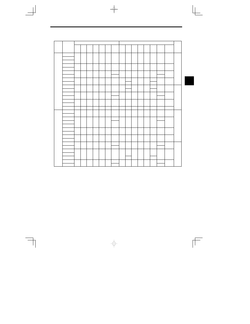
2.2
VS-626MC5 External Dimensions (mm) and Approx. Masses (kg)
Volt-
Max. Ap-
plicable
Open Chassis (IP00)
Enclosed Wall-mounted (NEMA1)
DC
Volt-
age
class
plicable
Motor Out-
put
[kW]
W
H
D
W1
H1
H2
Approx.
Mass
W
H
D
W1
H1
H2
Approx.
Mass
Mounting
Holes
d *1
DC
Reac-
tor
*1
0.4
0.75
140
280
160
126
266
7.0
3
140
280
160
126
266
7.0
3
M5
1.5
2.2
140
280
180
126
266
7 0
4 5
140
280
180
126
266
7 0
4 5
M5
O
3.7
140
280
180
126
266
7.0
4.5
140
280
180
126
266
7.0
4.5
M5
Op-
tion
5.5
200
300
205
186
285
8 0
5.5
200
300
205
186
285
8 0
5.5
M6
tion
7.5
200
300
205
186
285
8.0
6
200
300
205
186
285
8.0
6
M6
200 V
11
250
380
225
236
365
7 5
11
250
380
225
236
365
7.5
11
M6
200 V
class
15
250
380
225
236
365
7.5
11
250
400
225
236
365
27.5
11
M6
18.5
325
450
285
275
435
7 5
28
330
610
285
275
435
87.5
32
M6
22
325
450
285
275
435
7.5
28
330
675
285
275
435
152.5
32
M6
30
425
675
350
320
650
12 5
61
430
985
350
320
650
212 5
67
M10
B il
37
425
675
350
320
650
12.5
62
430
985
350
320
650
212.5
68
M10
Built-
in
45
475
800
350
370
775
12 5
80
480
1110
350
370
775
212 5
87
M10
in
55
475
800
350
370
775
12.5
80
480
1110
350
370
775
212.5
87
M10
75
575
925
400
445
895
15.0
135
580
1290
400
445
895
270
145
M12
0.4
140
280
160
126
266
7 0
3
140
280
160
126
266
7 0
3
M5
0.75
140
280
160
126
266
7.0
3
140
280
160
126
266
7.0
3
M5
1.5
4
4
2.2
140
280
180
126
266
7.0
4 5
140
280
180
126
266
7.0
4 5
M5
O
3.7
4.5
4.5
Op-
tion
5.5
200
300
205
186
285
8 0
6
200
300
205
186
285
8 0
6
M6
tion
7.5
200
300
205
186
285
8.0
6
200
300
205
186
285
8.0
6
M6
400 V
11
250
380
225
236
365
7 5
11
250
380
225
236
365
7 5
11
M6
400 V
class
15
250
380
225
236
365
7.5
11
250
380
225
236
365
7.5
11
M6
18.5
325
450
285
275
435
7 5
29
330
610
285
275
435
87 5
32
M6
22
325
450
285
275
435
7.5
31
330
610
285
275
435
87.5
34
M6
30
785
87 5
B il
37
325
625
285
275
610
7.5
44
330
785
285
275
610
87.5
48
M6
Built-
in
45
850
152.5
in
55
455
820
350
350
795
12 5
81
460
1130
350
350
795
212 5
87
M10
75
455
820
350
350
795
12.5
82
460
1130
350
350
795
212.5
88
M10
* 1. Same for open chsassis and enclosed wall-mounted types.
* 2. See page - 4 for mounting dimensions.
Note An attachment is required to mount the cooling fins (fin section) on the outside of the control panel for 200 V/400 V class
Inverters of 15 kW or less. Please ask your Yaskawa representative for details. Dimensional drawings for models with exter-
nally mounted cooling fins and other special requirements are also available from your Yaskawa representative.
2