Yaskawa VS-626 MC5 User Manual
Page 242
User Constants
8.2.10 Factory Settings that Change with the Control Method (A1-02)
- 34
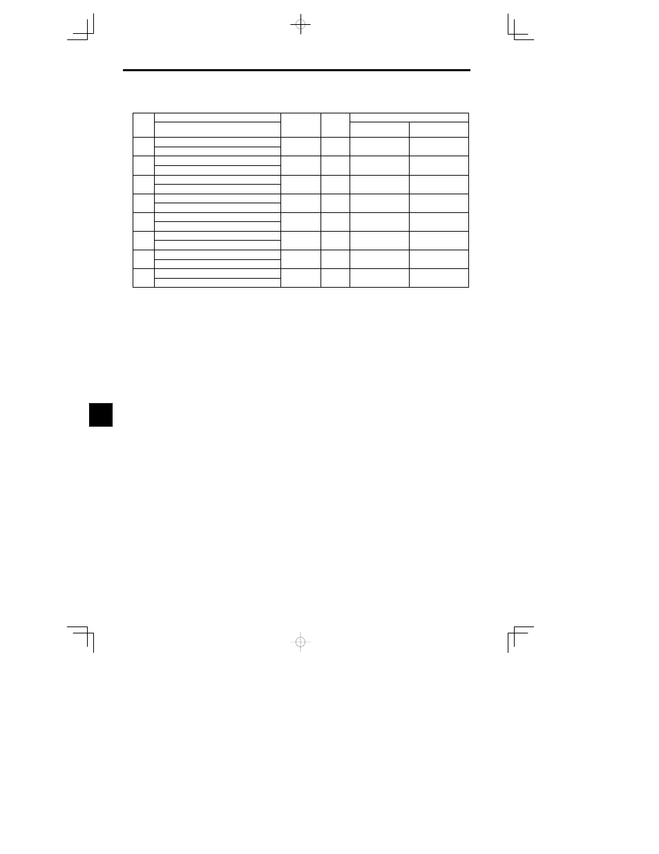
8.2.10 Factory Settings that Change with the Control Method (A1-02)
Con-
Name
Setting
Factory Setting
Con
stant
No.
Display
Setting
Range
Unit
Open Loop Vector
A1-02=2
Flux Vector
A1-02=3
b3-01
Speed search selection at start
0 1
1
0
1
b3-01
SpfSrch at Start
0 1
1
0
1
C3-01
Slip compensation gain
0 0 to 2 5
0 1
1 0
1 0
C3-01
Slip Comp gain
0.0 to 2.5
0.1
1.0
1.0
E1--04 Max. output frequency
0 0 to 400 0
0 1 Hz
60 0
60 0
E1 04
E4--01 Max Frequency
0.0 to 400.0
0.1 Hz
60.0
60.0
E1--05 Max. voltage
0 0 to 255 0
0 1 V
200 0
200 0
E1 05
E4--02 Max Voltage
0.0 to 255.0
0.1 V
200.0
200.0
E1--06 Max. voltage frequency
0 0 to 400 0
0 1 Hz
60 0
60 0
E1 06
E4--03 Max Voltage Frequency
0.0 to 400.0
0.1 Hz
60.0
60.0
E1-07
Mid. output frequency
0 0 to 400 0
0 1 Hz
3 0
0 0
E1 07
E4-04
Mid Frequency A
0.0 to 400.0
0.1 Hz
3.0
0.0
E1-08
Mid. output frequency voltage
0.0 to 255.0
0 1 V
11.0
0 0
E1 08
E4-05
Mid voltage A
0.0 to 255.0
(0.0 to 510.0)
0.1 V
11.0
(22.0)
0.0
E1-09
Min. output frequency
0 0 to 400 0
0 1 Hz
0 5
0 0
E1 09
E4-06
Min Frequency
0.0 to 400.0
0.1 Hz
0.5
0.0
Note Values in parentheses are for 400 V class Inverters.
8