Yaskawa VS-626 MC5 User Manual
Page 99
5.2
Trial Operation Procedures
- 5
5.2.4 Setting Input Voltage
Set the input voltage of the Inverter (E1-01) according to the power supply voltage.
J
Input Voltage: E1-01
Set the input voltage.
User
Change
during
Setting
Factory
Valid Access Levels
User
Constant
Number
Name
during
Opera-
tion
Setting
Range
Unit
Factory
Setting
Open Loop
Vector
Flux Vector
E1-01
Input voltage setting
155 to 255
(310 to 510)*
VAC
200
(400)*
Q
Q
*
Values in parentheses are for 400 V class Inverters.
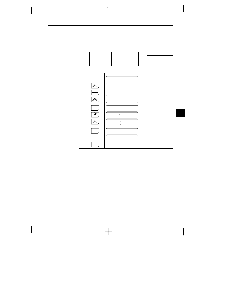
Use the following procedure to set a 200 V class Inverter to an input voltage of 230 V.
Step
Key Sequence
Digital Operator Display
Remarks
Main Menu
Initialize
Displays initialize mode.
1
Main Menu
Programming
Displays programming mode.
2
DATA
ENTER
Frequency Ref
Terminal
Puts the Unit in programming mode.
3
Press 10 times.
Input Voltage
E1-01
=
200 VAC
Displays the input voltage setting dis-
play.
4
DATA
ENTER
Input Voltage
200 VAC
The leading digit will blink
5
RESET
Input Voltage
200 VAC
The 2nd digit will blink.
6
Press 3 times.
Input Voltage
230 VAC
Set to “3”
7
DATA
ENTER
Entry Accepted
The set value is overwritten. “Entry
Accepted” is displayed for approxi-
mately 0.5 seconds.
Input Voltage
E1-01
=
230 VAC
Returns to the input voltage display.
Check that the data has been updated.
8
ESC
Main Menu
Programming
Returns to the programming mode
display.
J
Setting the Power Supply Voltage Jumper (400 V Class Inverters of 18.5 kW or
Higher)
Set the power supply voltage jumper after setting the input voltage constant (E1-01) for 400 V class Invert-
ers of 18.5 kW or higher. Insert the jumper into the voltage connector nearest to the actual power supply
voltage.
The jumper is factory-set to 440 V when shipped. If the power supply voltage is not 440 V, use the follow-
ing procedure to change the setting.
1. Turn OFF the power supply switch and wait for at least one minute (three minutes for models larger
than 30 kW) before removing the front panel and setting the jumper.
2. Remove the front cover.
3. Insert the jumper at the position for the voltage supplied to the Inverter (see Figure 5.1).
5