Yaskawa VS-626 MC5 User Manual
Page 163
7.3
Common Functions
- 25
J
Prohibited Frequencies (Jump Frequencies): d3-01 to d3-04
D
This function allows the prohibition or “jumping” of certain frequencies within the Inverter’s output
frequency range so that the motor can operate without resonant oscillations caused by some machine
systems.
D
It is also used for deadband control.
User
Change
during
Setting
Factory
Valid Access Levels
User
Constant
Number
Name
during
Opera-
tion
Setting
Range
Unit
Factory
Setting
Open Loop
Vector
Flux Vector
d3-01
Jump frequency 1
0.0 to 400.0
Hz
0.0
B
B
d3-02
Jump frequency 2
0.0 to 400.0
Hz
0.0
B
B
d3-03
Jump frequency 3
0.0 to 400.0
Hz
0.0
B
B
d3-04
Jump frequency width
0.0 to 20.0
Hz
1.0
B
B
D
To disable this function, set the jump frequency references (d3-01 to d3-03) to 0.0 Hz.
D
For d3-01 to d3-03, set the center values of the frequencies to be jumped. Be sure to set the jump fre-
quency so that d3-03
% d3-02 % d3-01.
D
For d3-04, set the jump frequency bandwidth. The jump frequency
r the jump frequency bandwidth
becomes the jump frequency range.
D
Operation is prohibited within the jump frequency range, but changes during acceleration and decel-
eration are smooth with no jumps.
D
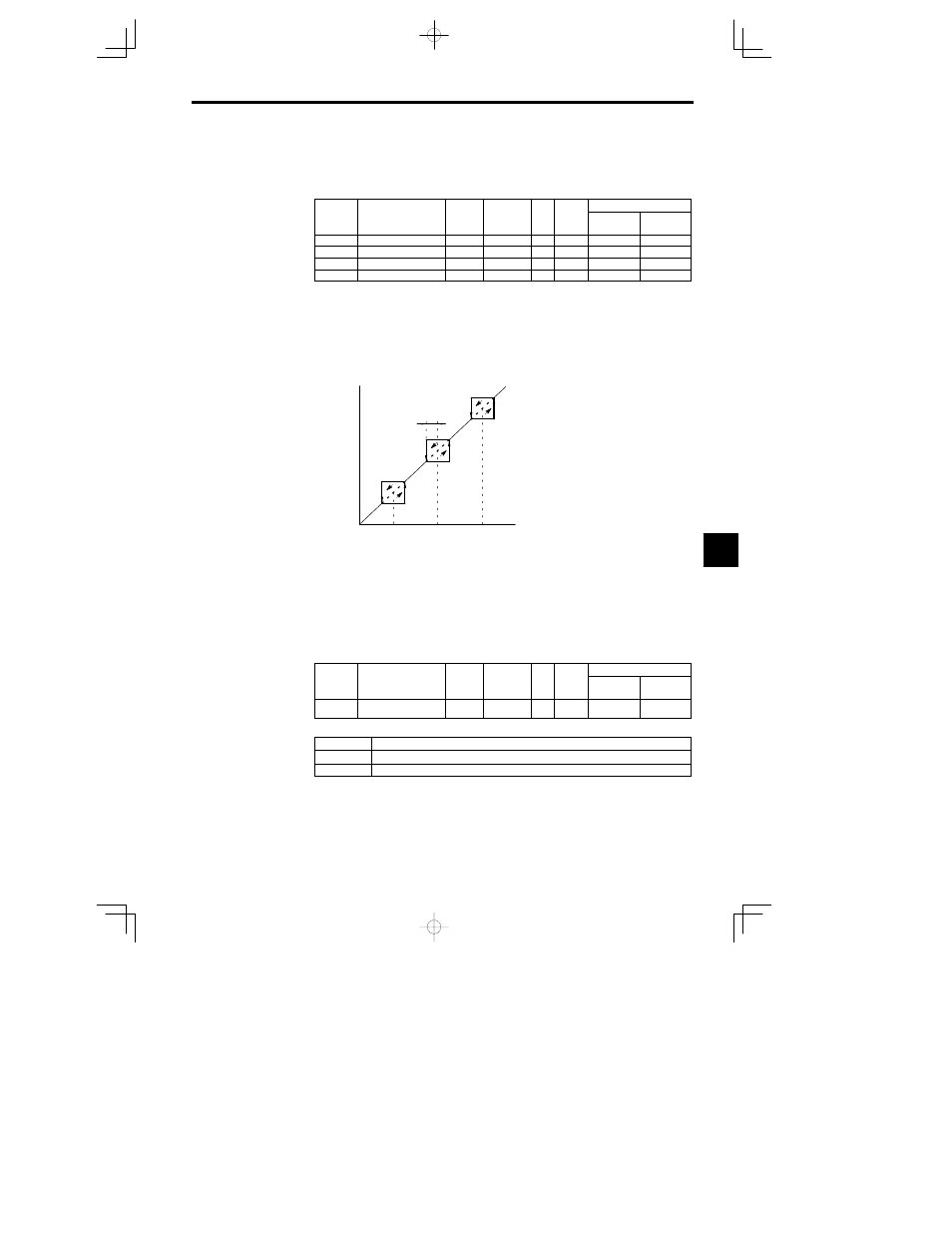
The relation between the internal frequency reference and the set frequency references is shown in Fig-
ure 7.14.
d3-04
d3-03
d3-02
d3-01
Internal frequency reference
Set frequency reference
Dotted lines show operation during
acceleration/deceleration.
Fig
7.14
Setting Prohibited Frequencies
J
Hold Reference Memory Selection: d4--01
D
Constant d4--01 is enabled by making either of the following settings for the multi--function inputs
(H1--01 to H1--06).
x
Acceleration/deceleration ramp hold (setting: A)
x
Up command (setting: 10)/down command (setting: 11)
D
When hold status is established by these external signals, specify whether or not the output frequency
is to be retained.
D
When this function is enabled, operation is re--started after power--up using the frequency reference
value that was retained.
User
Change
during
Setting
Factory
Valid Access Levels
User
Constant
Number
Name
during
Opera-
tion
Setting
Range
Unit
Factory
Setting
Open Loop
Vector
Flux Vector
d4-01
Frequency reference
hold function selection
0 1
--
0
A
A
D
Settings
Setting
Contents
0
Disabled. Restart after operation stoppage or power--up begins at zero.
1
Enabled. Restarr after operation stoppage or power--up begins at the held frequency reference.
D
For information regarding the acceleration/deceleration stop (hold) command and the up/down com-
mand, refer to the decription of Multi--function Input (H1).
J
Trim Control Level: d4--02
D
The trim control level is valid when the trim control increase command (setting: 1C) or trim control
decrease command (setting: 1D) is set for a multi--function input (H1--01 to H1--06).
7