Yaskawa VS-626 MC5 User Manual
Page 115
Basic Operation
6.1.7 Selecting the Stopping Method: b1-03
- 12
6.1.7 Selecting the Stopping Method: b1-03
D
Set the stopping method used when a stop command is input.
User
Change
during
Setting
Factory
Valid Access Levels
User
Constant
Number
Name
during
Opera-
tion
Setting
Range
Unit
Factory
Setting
Open Loop
Vector
Flux Vector
b1-03
Stopping method selec-
tion
0
--
0
Q
Q
D
Settings
Setting
Function
0
Deceleration to stop
D
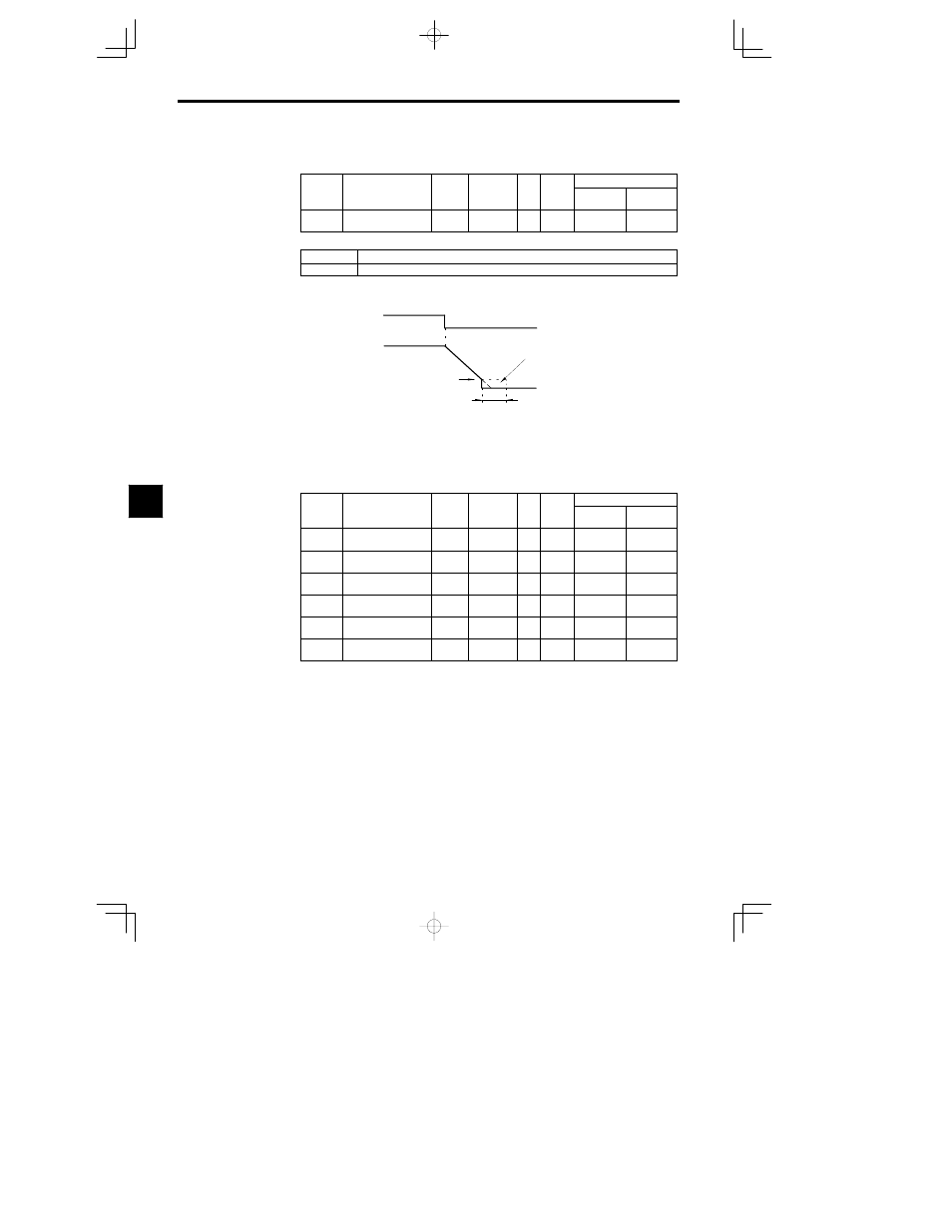
The following diagrams show the operation of the stopping method.
x
Deceleration to Stop (b1-03 = 0)
Run command
ON
OFF
Output frequency
Deceleration
time
DC injection braking
Excitation level (b2-01)
DC injection braking time at stop (b2-04)
Decelerates to a stop at a rate set with the selected deceleration time.
Fig
6.4
Deceleration to Stop
6.1.8 Multi-function Input Settings: H1-01 through H1-06
D
Set the functions for terminals 3 to 8. Set the functions of the multi-function inputs according to the
application.
User
Change
during
Setting
Factory
Valid Access Levels
User
Constant
Number
Name
during
Opera-
tion
Setting
Range
Unit
Factory
Setting
Open Loop
Vector
Flux Vector
H1-01
Multi-function input 1
(terminal 3)
0 to 77
--
24
B
B
H1-02
Multi-function input 2
(terminal 4)
0 to 77
--
14
B
B
H1-03
Multi-function input 3
(terminal 5)
0 to 77
--
3 (0)
B
B
H1-04
Multi-function input 4
(terminal 6)
0 to 77
--
4 (3)
B
B
H1-05
Multi-function input 5
(terminal 7)
0 to 77
--
6 (4)
B
B
H1-06
Multi-function input 6
(terminal 8)
0 to 77
--
8 (6)
B
B
D
The default settings in parentheses are the default values when the Unit is initialized for 3-wire se-
quence control.
D
The constant settings that are used most often are explained below. Refer to chapter NO TAG Advanced
Operation or the constant tables for details on the other settings.
S 3-wire sequence (forward/reverse run command):
Set “0”
S Multi-step sped references 1 to 3 and jog command:
Set “3” to “6”
S Acceleration/Deceleration Time Selectors 1 and 2:
Set “7” and “1A”
S Emergency Stop:
Set “15”
S FORWARD and REVERSE JOG References:
Set “12” and “13”
S Terminal 13/14 Switch:
Set “1F”
6