2 flux vector control – Yaskawa VS-626 MC5 User Manual
Page 148
Advanced Operation
- 10
7.2
Flux Vector Control
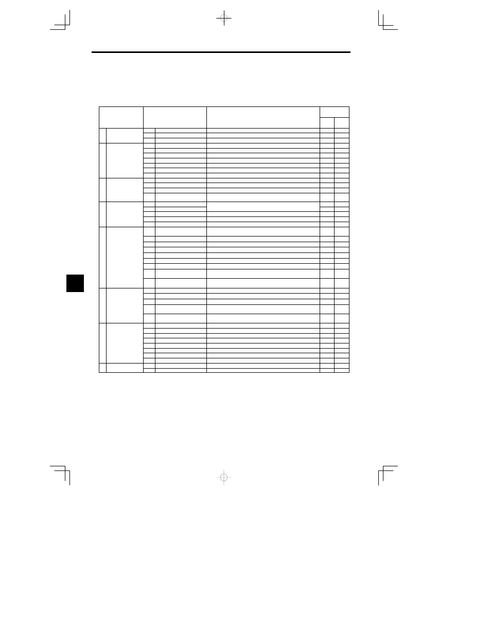
The functions that can be used with flux vector control are listed in Table 7.2. Details on functions that are spe-
cific to flux vector control (i.e. those marked with a ) are provided in the following table.
Table
7.2
Flux Vector Control Functions
Group
Function
Comments
Control Meth-
od
Group
Function
Comments
Open
Loop
Vector
Flux
Vector
b1
Sequence
Settings such as the reference input method
b
Application
b2
DC Injection Braking
DC injection braking function settings
b
Application
b3
Speed Search
Speed search function settings
C1
Accel/Decel
Acceleration/deceleration time settings
C2
S-Curve Acc/Dec
S-curve characteristics for accel/decel times
C3
Motor-Slip Compensation
Motor temperature compensation function adjustment
C Tuning
C4
Torque Compensation
Not used. (Can’t be set.)
C Tuning
C5
Speed Controls
Speed control loop adjustment
C6
Carrier Frequency
Carrier frequency settings
C8
Factory Tuning
Not used. (Can’t be set.)
d1
Preset Reference
Frequency reference settings (when using Operator)
d2
Reference Limits
Frequency upper and lower limit settings
d
Reference
d3
Jump Frequencies
Prohibited frequency settings
d4
Reference frequency hold
function
Up/Down, Accel/Decel stop hold frequency setting
E1
V/f Pattern
Motor constant settings
E2
Motor Setup
Motor constant settings
(Motor constants set automatically with autotuning.)
E
Motor
E3
Motor 2 Control Methods
Control method settings for motor 2.
E
Motor
E4
Motor 2 V/f Characteristics
V/f characteristics settings for motor 2.
E5
Motor 2 Motor Constants
Motor constant settings for motor 2.
F1
PG Speed Control Card
Settings
Constant settings for a PG Speed Control Card
F2
Analog Reference Card AI
User constant settings for an Analog Reference Card
F3
Digital Reference Card DI
User constant settings for a Digital Reference Card
F4
Analog Monitor Card AO
User constant settings for an Analog Monitor Card
F
Options
F5
Digital Output Card DO
User constant settings for a Digital Output Card
F
Options
F6
Digital Output Card DO
User constant settings for a Digital Output Card
F7
Pulse Monitor Card PO
User constant settings for a Pulse Monitor Card
F8
SI-F/SI-G Transmission
Card
User constant settings for a Transmission Card
F9
CP-916B Transmission
Card
User constant settings for a Transmission Card
H1
Multi-function Inputs
Function selection for multi-function inputs
H2
Multi-function Outputs
Function selection for multi-function outputs
H T
i
l
H3
Analog Inputs
Function selection for analog inputs
H Terminal
H4
Multi-function Analog Out-
puts
Function selection for analog outputs
H5
MEMOBUS Communica-
tions
MEMOBUS communications settings
L1
Motor Overload
Sets electrical/thermal functions that protect the motor.
L2
Power Loss Ridethru
Selects the power-loss processing method.
L3
Stall Prevention
Accel/Decel stall prevention settings and selection
L
Protection
L4
Reference Detection
Frequency detection settings and selection
L
Protection
L5
Fault Restart
Fault restart function settings
L6
Torque Detection
Sets overtorque detection functions 1 and 2 (by current)
L7
Torque Limit
Torque limit function settings
L8
Hardware Protection
Hardware overheating and open-phase protection settings
o
Operator
o1
Monitor Select
Selects the Operator’s display and setting methods.
o
Operator
o2
Key Selections
Operator’s key function selection and other constants
7