Yaskawa VS-626 MC5 User Manual
Page 166
Advanced Operation
7.3.4 Option Constants: F
- 28
J
Digital Reference Card: F3-01
D
When using a DI-08 or DI-16H2 Digital Reference Card, set constant b1-01 (reference selection) to
“3” (option) and set the input method with constant F3-01.
User
Change
during
Setting
Factory
Valid Access Levels
User
Constant
Number
Name
during
Opera-
tion
Setting
Range
Unit
Factory
Setting
Open Loop
Vector
Flux Vector
F3-01
Digital input option
0 to 7
--
0
B
B
D
Settings
Setting
Description
0
BCD 1% unit
1
BCD 0.1% unit
2
BCD 0.01% unit
3
BCD 1 Hz unit
4
BCD 0.1 Hz unit
5
BCD 0.01 Hz unit
6
BCD special setting (5-digit input) (Only when DI-16H2 is used.)
7
Binary input (Setting is displayed in decimal notation.)
D
The maximum frequency (100% speed) reference will be used when the binary input is set (setting:
7) and all bits are “1.”
x
DI-08:
Maximum output frequency reference (255/100%).
x
DI-16H2:
Maximum output frequency reference (16 bits: 30000/100%, 12 bits: 4095/100%).
D
Setting 6, BCD special setting (5-digit input), is valid only when the D1-16H2 is used. Using this set-
ting, a frequency from 0.00 to 399.98 Hz can be set in BCD. The data input method is different from
that for settings of 1 to 5.
Setting: 1 to 5
Sign
8
10
3
4
10
3
2
10
3
1
10
3
8
10
0
4
10
0
2
10
0
1
10
0
Setting: 6
2
10
4
1
10
4
8
10
3
4
10
3
2
10
3
1
10
1
8
10
0
4
10
0
2
10
0
D
The sign bit is used as a data bit, so only positive (plus) data can be set.
D
The second digit below the decimal point is set by bits 8x10
0
, 4x10
0
, and 2x10
0
, so the settings are
made in units of 0.02 Hz. (If these three bits are “111,” “110,” and “101,” they will be recognized as
“9.”)
J
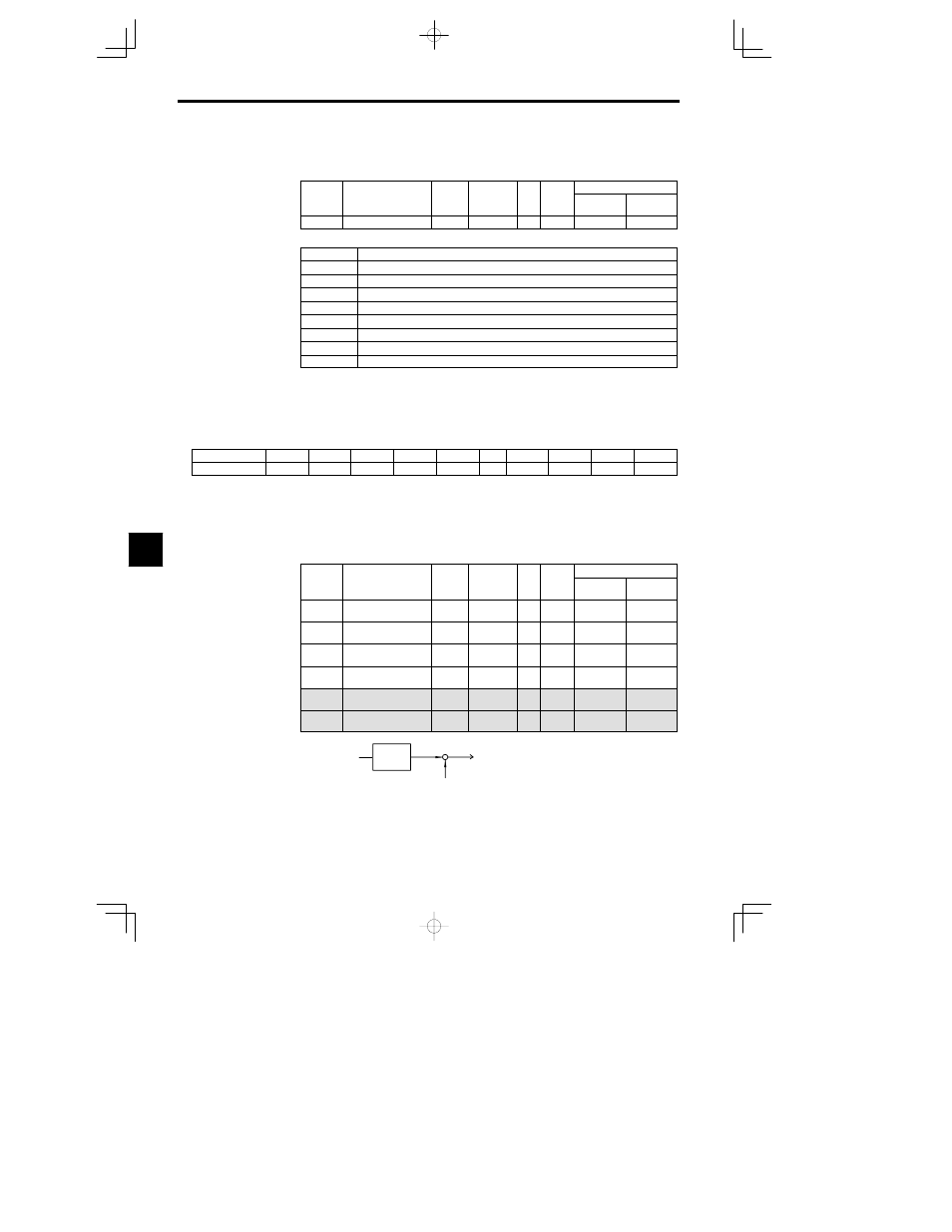
Analog Monitor Card: F4-01 to F4-04
D
When using an AO-08 or AO-12 Analog Monitor Card, set the monitor items and gain with the follow-
ing constants.
User
Change
during
Setting
Factory
Valid Access Levels
User
Constant
Number
Name
during
Opera-
tion
Setting
Range
Unit
Factory
Setting
Open Loop
Vector
Flux Vector
F4-01
Channel 1 monitor
selection
1 to 38
--
2
B
B
F4-02
Channel 1 gain
0.00 to 2.50
Mul-
tiple
1.00
B
B
F4-03
Channel 2 monitor
selection
1 to 38
--
3
B
B
F4-04
Channel 2 gain
0.00 to 2.50
Mul-
tiple
0.50
B
B
F4--05
Channel 1 output bias
--10.0 to
+10.0
%
0.0
B
B
F4--06
Channel 2 output bias
--10.0 to
+10.0
%
0.0
B
B
F4--02
(F4--04)
A
O
+
+
F4--05
(F4--06)
Output gain
Output bias
Fig
7.16
Analog Output Block Diagram
7