Yaskawa VS-626 MC5 User Manual
Page 195
7.3
Common Functions
- 57
D
The settings in the torque detection selection constants (L6-01 and L6-04) determine whether overtor-
que conditions will be detected and what kind of processing will be performed if a overtorque condi-
tion is detected.
D
L6-01/L6-04 Settings
Setting
Function
Display
0
Overtorque detection disabled
Overtorque detection 1
Overtorque output 2
1
Detect only during speed agree. Continue
operation even after detection. (Minor
fault)
“OL3” blinks
“OL4” blinks
2
Detect overtorque at any time. Continue
operation even after detection. (Minor
fault)
“OL3” blinks
“OL4” blinks
3
Detect only during speed agree. Stop out-
put after detection. (Fault
)
“OL3” lights
“OL4” lights
4
Detect overtorque at any time. Stop output
after detection. (Fault)
“OL3” lights
“OL4” lights
D
When overtorque detection is enabled, be sure to set the overtorque detection level (L6-02 or L6-05)
and the overtorque detection time (L6-02 or L6-05). An overtorque condition is detected when the cur-
rent exceeds the overtorque detection level for longer than the overtorque detection time.
D
The overtorque detection level is set as a percentage of the motor rated torque.
D
Any of the following functions can be set in a multi-function output (H2-01, H2-02, or H2-03) to indi-
cate fact that an overtorque condition has been detected.
S Setting B: Overtorque detection 1 (NO)
S Setting 18: Overtorque detection 2 (NO)
S Setting 17: Overtorque detection 1 (NC)
S Setting 19: Overtorque detection 2 (NC)
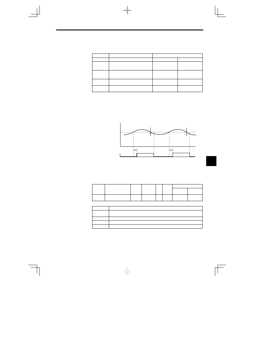
Motor current
(Output torque)
L6-02 or L6-05
Overtorque Detection 1 (N.O.)
or Overtorque Detection 2
(N.O.)
ON
L6-03
or
L6-06
ON
L6-03
or
L6-06
*
The overtorque detection is cleared when the current drops about 5% of the
Inverter’s rated current (or the motor’s rated torque).
Fig
7.33
Timing Chart for Overtorque Detection
J
Hardware Protection Settings: L8-01 to L8-03, L8-05, L8-07
Protection Selection for Internal DB Resistor: L8-01
User
Change
during
Setting
Factory
Valid Access Levels
User
Constant
Number
Name
during
Opera-
tion
Setting
Range
Unit
Factory
Setting
Open Loop
Vector
Flux Vector
L8-01
Protect selection for in-
ternal DB resistor
0 to 3
--
0
B
B
D
Settings
Setting
Function
0
Disabled. (Select 0 when a braking resistor isn’t being used or a Braking Resistor Unit is being
used.)
1
Enabled. (Protects the braking resistor from overheating.)
2
3%ED
3
10%ED
7