Yaskawa VS-626 MC5 User Manual
Page 175
7.3
Common Functions
- 37
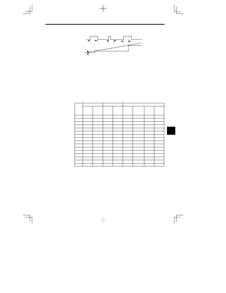
Sample/hold
command
Analog input
Frequency
reference
CLOSED
100
ms
100
ms
100
ms
CLOSED
CLOSED
Fig
7.21
Analog Frequency Reference Sample/Hold
D
The analog frequency reference sample/hold function is valid only for terminals 13, 14, and 16 or for
the analog inputs from the AI-14U or AI-14B.
D
An OPE03 fault will occur if two or more of the following signals turn ON at the same time: accelera-
tion/deceleration ramp hold command (0A), up/down commands (10 or 11), trim control increase/de-
crease commands (1C or 1D), and the analog frequency reference sample/hold command.
External Faults (Settings: 20 to 2F)
D
With this setting, the multi-function input can be used to stop the Inverter or output an alarm when a
malfunction or fault occurs in a peripheral device.
D
There are 16 external fault inputs available with all 16 combinations of the following variables. Select
the setting with the desired combination.
x
Input level:
Normally open or normally closed
x
Detection method:
Always or During operation only
x
Operation selection:
Deceleration to stop, Coast to stop, Emergency stop, or Continue opera
tion
Table
7.6
External Fault Settings
Input level
Detection method
Operation selection
Setting
NO con-
tact
NC con-
tact
Always
During
operation
Decel-
eration to
stop
(Fault)
Coast to
stop (Fault)
Emer-
gency
stop
(Fault)
Continue
operation
(Alarm)
20
21
22
23
24
25
26
27
28
29
2A
2B
2C
2D
2E
2F
D
For the input level, select whether you want a fault to be detected when the input signal is ON (normally
open input) or OFF (normally closed input).
D
For the detection method, select whether you want faults to be detected any time that the Inverter is
ON or only during operation.
7