Yaskawa VS-626 MC5 User Manual
Page 205
7.4
Optional Functions
- 67
D
Settings
Setting
Function
0
Motor 1 constants (E1, E2) are used for Y-winding, and motor 2 constants (E3, E4, E5) are used
for -winding
1
Motor 2 constants (E3, E4, E5) are used for Y-winding, and motor 2 constants (E1, E2) are used
for -winding
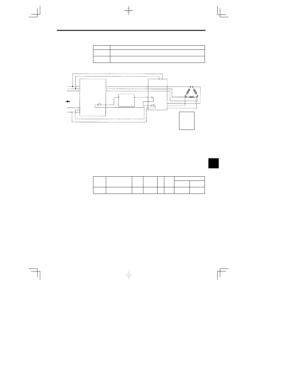
Fig 7.37 shows a wiring example of external winding change.
B1-02 = 4
H1-05 = 80
H1-06 = 82
H2-01 = 41
A1-02 = 2
E3-01 = 2
3
230 V
R
T
S
From CNC
Winding change
Common
7
11
8
U
W
V
9
10
VS--626MC5
1
230 V
0 V
24 V
+24 VDC
Supply
MC Answerback
17 18
2
6
4
13
14
15
16
HV--75AP3
Megnetic Contactor
Dual Winding
Motor
U
Z
X
V
Y
W
Fig
7.37
Sample Wiring for External Wiring Change
(Open Loop Vector Control Mode)
D
To use the external winding change method, set the multi-function digital input used for receiving the
winding change signal to “80.” This setting enables the selection of Motor 1 constants (E1 and E2)
when the input is open and Motor 2 constants (E4 and E5) when the input is closed.
D
When using the external winding change method, Auto-Winding constants (P1-01 and P1-02) are not
valid.
J
Auto-Winding Change Method
This method can be used when the multi-function digital input is not set to “80.”
The selection of the motor 1 and motor 2 is conducted internally by preset constants, such as winding
change frequency (P1-01) and winding change hysteresis ( P1-02).
Winding change frequency: P1-01
User
Change
during
Setting
Factory
Valid Access Levels
User
Constant
Number
Name
during
Opera-
tion
Setting
Range
Unit
Factory
Setting
Open Loop
Vector
Flux Vector
P1-01
Winding change fre-
quency
0.0 to 400.0
Hz
0.0
A
A
D
Sets winding change frequency when auto-winding change metod is used. Set P1-01 lower than the
max. frequency of the Y-winding.
7