Yaskawa VS-626 MC5 User Manual
Page 61
Wiring
3.7.4 Wiring PG Speed Control Card Terminal Blocks
- 28
3.7.4 Wiring PG Speed Control Card Terminal Blocks
Use no more than 100 meters of wiring for PG (encoder) signal lines, and keep them separate from power
lines.
Use shielded, twisted-pair wires for pulse inputs and pulse output monitor wires, and connect the shield
to the shield connection terminal.
J
Wire Sizes (Same for All Models)
Terminal wire sizes are shown in Table 3.12.
Table
3.12
Wire Sizes
Terminal
Terminal
Screws
Wire Thick-
ness mm
2
Wire Type
Pulse generator power supply
Pulse input terminal
Pulse monitor output terminal
Stranded wire: 0.5 to
1.25
Single wire: 0.5 to 1.25
S Shielded, twisted-pair wire
S Shielded,
polyethylene-cov-
ered vinyl sheath cable
Shield connection terminal
M3.5
0.5 to 2
ered, vinyl sheath cable
J
Solderless Terminals for Control Circuit Terminals
The use of solderless terminals for the control circuit terminals is recommended because solderless termi-
nals are easy to connect securely.
Table
3.13
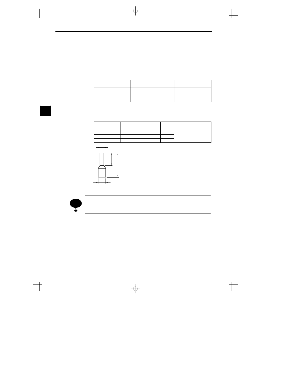
Straight Solderless Terminal Sizes
Wire Thickness
Model
d1
d2
Manufacturer
0.5 mm
2
A1 0.5-8 WH
1.00
2.60
0.75mm
2
A1 0.75-8 GY
1.20
2.80
Phoenix Contact
1 mm
2
A1 1-8 RD
1.40
3.00
Phoenix Contact
1.5 mm
2
A1 1.5-8 BK
1.70
3.50
d1
8 mm
14 mm
d2
Fig
3.26
Straight Solderless Terminal Sizes
Do not solder wires with the control circuit terminals if wires are used instead of solderless terminals.
Wires may not contact well with the control circuit terminals or the wires may be disconnected from the con-
trol circuit terminals due to oscillation if the wires are soldered.
3
NOTE