Yaskawa VS-626 MC5 User Manual
Page 50
3.4
Wiring Main Circuit Terminals
- 17
J
Connecting the Braking Resistor (ERF)
Connect the braking resistor as shown in Figure 3.14. When using a Braking Resistor Unit.
L8--01
Protect selection for
internal DB resistor
(Type ERF)
0: Disabled (no overheating protection)
1: Enabled (overheating protection)
L3--04
Stall prevention
selection during decel
0: Disabled (Deceleration as set. If deceleration time is too short, a main cir--
cuit overvoltage may result.)
1: Enabled (Deceleration is stopped when the main circuit voltage exceeds the
overvoltage level. Deceleration restarts when voltage is returned.)
2: Intelligent deceleration mode (Deceleration rate is automatically adjusted so
that in Inverter can decelerate in the shortest possible time. Set deceleration
time is desregarded.)
3: Enabled (with Braking Resistor Unit)
When a braking option (Braking Resistor, Braking Resistor Unit, Braking
Unit) is used, always set to 0 or 3.
VS-626MC5
B1
B2
Braking resistor
The braking resistor connection terminals are
B1 and B2. Do not connect to any other termi-
nals. Connecting to any terminals other than
B1 or B2 can cause the resistor to overheat,
resulting in damage to the equipment.
Fig
3.14
Connecting the Braking Resistor
J
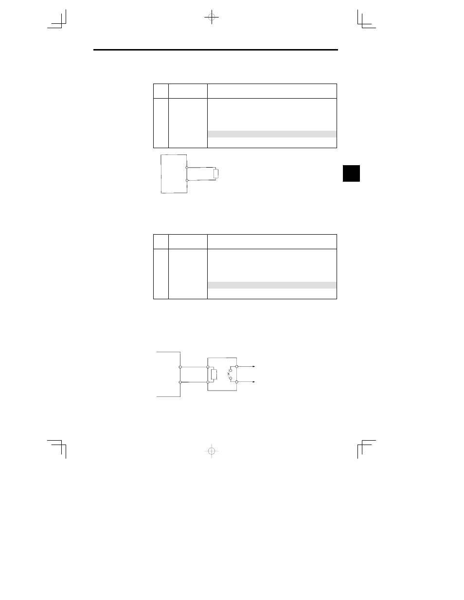
Connecting the Braking Resistor Unit (LKEB) and Braking Unit (CDBR)
Connect the Braking Resistor Unit and Braking Unit to the Inverter as shown in the Figure 3.15. Using
the Inverter with the Braking Resistor Unit connected.
L8--01
Protect selection for
internal DB resistor
(Type ERF)
0: Disabled (no overheating protection)
1: Enabled (overheating protection)
L3--04
Stall prevention selec-
tion during decel
0: Disabled (Deceleration as set. If deceleration time is too short, a main cir--
cuit overvoltage may result.)
1: Enabled (Deceleration is stopped when the main circuit voltage exceeds the
overvoltage level. Deceleration restarts when voltage is returned.)
2: Intelligent deceleration mode (Deceleration rate is automatically adjusted so
that in Inverter can decelerate in the shortest possible time. Set deceleration
time is desregarded.)
3: Enabled (with Braking Resistor Unit)
When a braking option (Braking Resistor, Braking Resistor Unit, Braking
Unit) is used, always set to 0 or 3.
Set L8-01 to “1” before operating the Inverter with the braking resistor without thermal overload relay trip
contacts.
The Braking Resistor Unit cannot be used and the deceleration time cannot be shortened by the Inverter
if L3-04 is set to “1” (i.e., if stall prevention is enabled for deceleration).
To prevent the Unit from overheating, design the sequence to turn OFF the power supply for the thermal
overload relay trip contacts of the Unit as shown in Figure 3.15.
200 V Class Inverters with 3.7 to 7.5 kW Output and
400 V Class Inverters with 3.7 to 15 kW Output
VS-626MC5
B1
B2
P
B
LKEB Braking Re-
sistor Unit
1
2
Thermal overload
relay trip contact
3