Yaskawa VS-626 MC5 User Manual
Page 46
3.4
Wiring Main Circuit Terminals
- 13
3.4.5 Wiring the Main Circuits
This section describes wiring connections for the main circuit inputs and outputs.
J
Wiring Main Circuit Inputs
Installing a Molded-case Circuit Breaker
Always connect the power input terminals (R, S, and T) and power supply via a molded-case circuit break-
er (MCCB) suitable for the Inverter.
D
Choose an MCCB with a capacity of 1.5 to 2 times the Inverter’s rated current.
D
For the MCCB’s time characteristics, be sure to consider the Inverter’s overload protection (one min-
ute at 150% of the rated output current).
D
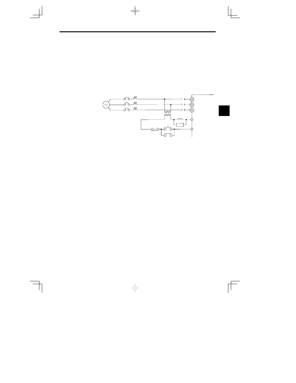
If the same MCCB is to be used for more than one Inverter, or other devices, set up a sequence so that
the power supply will be turned OFF by a fault output, as shown in Figure 3.7.
200 V class
:
3-phase,
200 to 230 VAC,
50/60 Hz
400 V class
:
3-phase,
380 to 460 VAC,
50/60 Hz
Power
supply
MCCB
MC
VS-626MC5
R
S
T
MC
SA
OFF
ON
MC
19
20
Fault output
(NC)
*
For 400 V class Inverters, connect a 400/200 V transformer.
Fig
3.7
MCCB Installation
Installing a Ground Fault Interrupter
Inverter outputs use high-speed switching, so high-frequency leakage current is generated. Therefore, at
the Inverter primary side, use a ground fault interrupter that detects only the leakage current in the frequen-
cy range that is hazardous to humans and excludes high-frequency leakage current.
D
For the special-purpose ground fault interrupter for Inverters, choose a ground fault interrupter with
a sensitivity amperage of at least 30 mA per Inverter.
D
When using a general ground fault interrupter, choose a ground fault interrupter with a sensitivity am-
perage of 200 mA or more per Inverter and with an operating time of 0.1 s or more.
Installing a Magnetic Contactor
If the power supply for the main circuit is to be shut off during a sequence, a magnetic contactor can be
used instead of a molded-case circuit breaker.
When a magnetic contactor is installed on the primary side of the main circuit to forcibly stop the Inverter,
however, the regenerative braking does not work and the Inverter will coast to a stop.
D
The Inverter can be started and stopped by opening and closing the magnetic contactor on the primary
side. Frequently opening and closing the magnetic contactor, however, may cause the Inverter to break
down.
D
When the Inverter is operated with the Digital Operator, automatic operation cannot be performed after
recovery from a power interruption.
D
If the Braking Resistor Unit is used, program the sequence so that the magnetic contactor is turned OFF
by the contact of the Unit’s thermal overload relay.
Connecting Input Power Supply to the Terminal Block
Input power supply can be connected to any terminal R, S or T on the terminal block; the phase sequence
of input power supply is irrelevant to the phase sequence.
Installing an AC Reactor
If the Inverter is connected to a large-capacity power transformer (600 kW or more) or the phase advancing
capacitor is switched, an excessive peak current may flow through the input power circuit, causing the con-
verter unit to break down.
To prevent this, install an optional AC Reactor on the input side of the Inverter or a DC reactor to the DC
reactor connection terminals.
This also improves the power factor on the power supply side.
3