Yaskawa VS-626 MC5 User Manual
Page 51
Wiring
3.4.5 Wiring the Main Circuits
- 18
200 V Class Inverters with 11 kW or higher Output and
400 V Class Inverters with 18.5 or higher Output
VS-626MC5
P
B
LKEB Braking Re-
sistor Unit
1
2
Thermal protector
trip contact
CDBR Braking
Unit
Thermal overload
relay trip contact
©
¨
3
©
¨
©
0
¨
0
3
4
Fig
3.15
Connecting the Braking Resistor Unit and Braking Unit
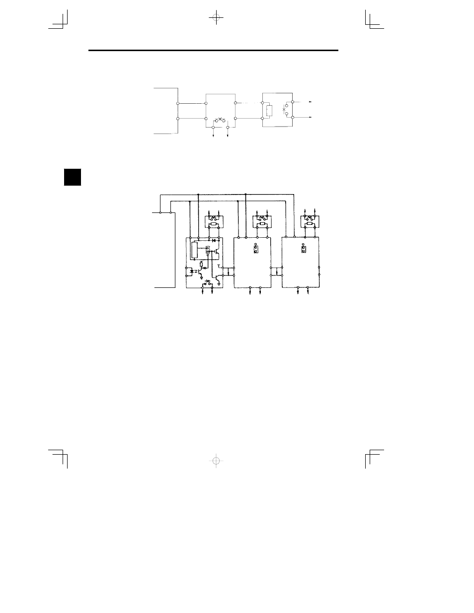
Connecting Braking Units in Parallel
When connecting two or more Braking Units in parallel, use the wiring and connectors shown in Figure
3.16. There are connectors for selecting whether each Braking Unit is to be a Master or Slave. Select “Mas-
ter” for the first Braking Unit only, and select “Slave” for all other Braking Units (i.e., from the second
Unit onwards).
Braking resistor overheat-
ing contacts (Thermal
protector contacts)
1
2
Braking
Resistor
Unit
¨
Level
detector
MASTER
SLAVE
+15
Braking Unit #2
MASTER
SLAVE
Cooling fin overheating
contacts (thermoswitch
contacts)
Braking Unit #1
¨
3
©
VS-626MC5
©
¨
0
©
0
Braking Unit #
3
MASTER
SLAVE
4
3
4
3
4
3
1
2
1
2
1
2
5
6
P
5
6
P
5
6
¨
©
¨
0
©
0
¨
©
¨
0
©
0
P
B
1
2
Braking
Resistor
Unit
P
B
1
2
Braking
Resistor
Unit
P
B
Braking resistor overheat-
ing contacts (Thermal
protector contacts)
Cooling fin overheating
contacts (thermoswitch
contacts)
Braking resistor overheat-
ing contacts (Thermal
protector contacts)
Cooling fin overheating
contacts (thermoswitch
contacts)
Fig
3.16
Connecting Braking Units in Parallel
3