Yaskawa VS-626 MC5 User Manual
Page 223
8.2
Programming Mode Constants
- 15
J
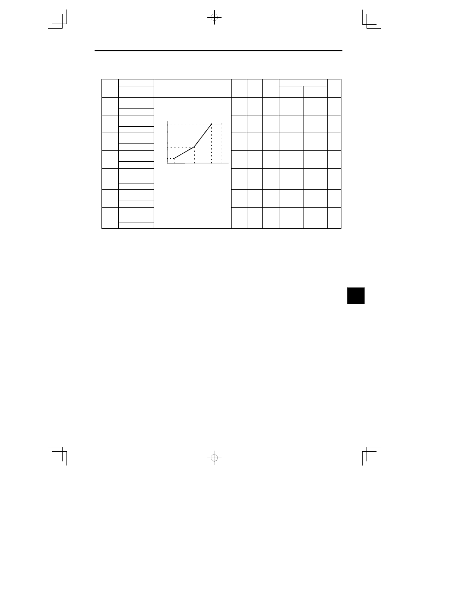
Motor 2 V/f Pattern: E4
Consta
nt
Name
Set-
Facto-
Change
during
Control Methods
nt
Num-
ber
Display
Description
Set
ting
Range
Facto
ry Set-
ting
g
during
Opera-
tion
Open Loop
Vector
Flux Vector
Page
E4-01
Motor 2 max. out-
put frequency
40.0 to
400 0
60.0
A
----
E4 01
V/F2 Max Freq
400.0
60.0
A
----
E4-02
Motor 2 max.
voltage
Output voltage (V)
VMAX
E4-02
0.0 to
255 0*
200*
A
----
E4 02
V/F2 Max Voltage
E4-02
255.0*
200
A
----
E4-03
Motor 2 max.
voltage frequency
0.0 to
400 0
60.0
A
----
E4 03
V/F2 Base Freq
VC
E4-05
400.0
60.0
A
----
E4-04
Motor 2 mid. out-
put frequency 1
E4-05
VMIN
E4-07
Fre-
quency
(
Hz
)
0.0 to
400 0
3.0
A
----
E4 04
V/F2 Mid Freq
E4-07
FMIN
FB
FA
FMAX
(
Hz
)
400.0
3.0
A
----
E4-05
Motor 2 mid. out-
put frequency
voltage 1
To set V/f characteristics in a straight
li
t th
l
f
E4 04
d
FMIN
E4-06
FB
E4-04
FA
E4-03
FMAX
E4-01
0.0 to
255.0*
11.0*
A
----
V/F2 Mid Voltage
/
g
line, set the same values for E4-04 and
E4-06. In this case, the setting for
255.0
E4-06
Motor 2 min. out-
put frequency
E4-06. In this case, the setting for
E4-05 will be disregarded.
Always ensure that the four frequen-
cies are set in the following manner:
0.0 to
400 0
0.5
A
----
E4 06
V/F2 Min Freq
cies are set in the following manner:
E4-01 (FMAX)
E4-03 (FA)
E4-04
(FB)
E4 06 (FMIN)
400.0
0.5
A
----
E4-07
Motor 2 min. out-
put frequency
voltage
(
)
(
)
(FB)
E4-06 (FMIN)
0.0 to
255.0*
2.0*
A
----
V/F2 Min Voltage
255.0
*
When the control method is changed, the Inverter reverts to factory settings. (The open loop vector control factory settings are
given.)
8