Yaskawa VS-626 MC5 User Manual
Page 222
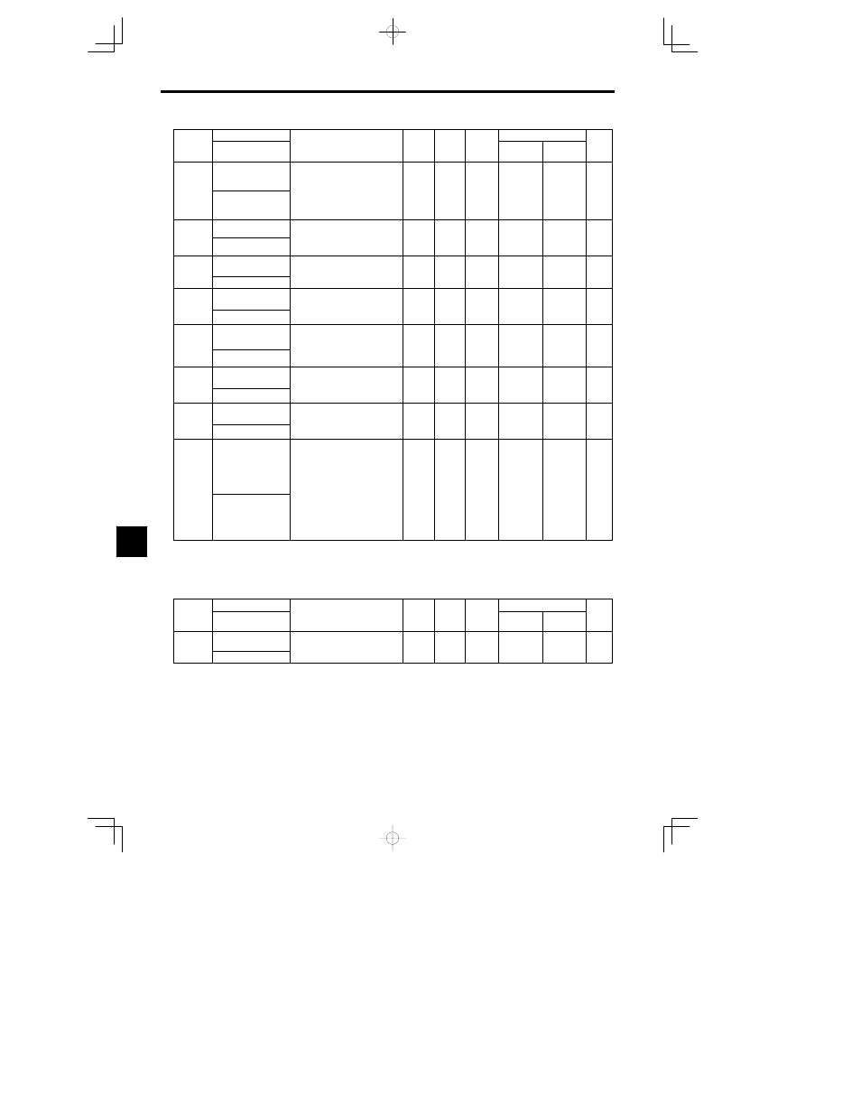
User Constants
8.2.4 Motor Constant Constants: E
- 14
Constant
Number
Page
Control Methods
Change
during
Opera-
tion
Factory
Setting
Setting
Range
Description
Name
Constant
Number
Page
Flux Vector
Open Loop
Vector
Change
during
Opera-
tion
Factory
Setting
Setting
Range
Description
Display
E2-02
Motor rated slip
Sets the motor rated slip in Hz
units.
These set values will become the
f
l
f
li
0.00 to
2.90
Q
Q
- 6
E2-02
Motor Rated Slip
reference values for slip com-
pensation.
These values will be automati-
cally set during autotuning.
0.00 to
20.00
2.90
*1
Q
Q
6
- 13
E2-03
Motor no-load current
Sets the motor no-load current in 1
A units.
0.00 to
1.20
Q
Q
- 7
E2-03
No-Load Current
u ts.
These values will be automatical-
ly set during autotuning.
0.00 to
1500.0
1.20
*1
Q
Q
7
- 13
E2-04
Number of motor
poles
Sets the number of motor poles.
These values will automatically
2 to 48
4
Q
- 14
E2 04
Number of Poles
These values will automatically
be set during autotuning.
2 to 48
4
Q
- 14
E2-05
Motor line-to-line re-
sistance
Sets the motor phase-to-phase re-
sistance in
: units.
Th s
l
s
ill b
tom tic l
0.000 to
65 000
9.842
*1
A
A
- 7
14
E2 05
Term Resistance
These values will be automatical-
ly set during autotuning.
65.000
*1
A
A
- 14
E2-06
Motor leak induc-
tance
Sets the voltage drop due to motor
leakage inductance as a percentage
of the motor rated voltage.
0.0 to
30 0
18.2
A
A
- 7
14
E2 06
Leak Inductance
of the motor rated voltage.
These values will be automatical-
ly set during autotuning.
30.0
18.2
A
A
- 14
E2-07
Motor iron-core satu-
ration coefficient 1
Sets the motor iron-core saturation
coefficient at 50% of magnetic flux.
Th s
l
s
ill b
tom tic l
0.00 to
0 50
0.50
A
A
- 7
- 15
E2 07
Saturation Comp 1
These values will be automatical-
ly set during autotuning.
0.50
0.50
A
A
- 15
E2-08
Motor iron-core satu-
ration coefficient 2
Sets the motor iron-core saturation
coefficient at 75% of magnetic flux.
Th s
l
s
ill b
tom tic l
0.00 to
0 75
0.75
A
A
- 7
15
E2 08
Saturation Comp 2
These values will be automatical-
ly set during autotuning.
0.75
0.75
A
A
- 15
E2-09
Motor mechanical
loss
Sets motor mechanical loss as a
percentage of motor rated output
(W).
Usually setting is not necessary.
Adjust in the following circum-
stances:
S When torque loss is large due to
0.0 to
10 0
0.0
A
- 15
E2 09
Mechanical Loss
S When torque loss is large due to
motor bearing.
S When the torque loss in the pump
or fan is large.
The set mechanical loss will com-
pensate for torque.
10.0
0.0
A
- 15
* 1. The factory setting depends upon the Inverter capacity. The values for a 200 V class Inverter of 0.4 kW are given. See page
- 35.
* 2. The setting range is 10% to 200% of the Inverter’s rated output current. The value for a 200 V class Inverter of 0.4 kW is given.
J
Motor 2 Control Method: E3
Constant
Name
Setting
Factory
Change
during
Control Methods
Constant
Number
Display
Description
Setting
Range
Factory
Setting
g
during
Opera-
tion
Open Loop
Vector
Flux Vector
Page
E3-01
Motor 2 control meth-
od selection
2: Open loop vector
3: Flux vector control
2 3
2
A
----
E3 01
Control Method
3: Flux vector control
2 3
2
A
----
8