Yaskawa VS-626 MC5 User Manual
Page 182
Advanced Operation
7.3.5 External Terminal Functions: H
- 44
J
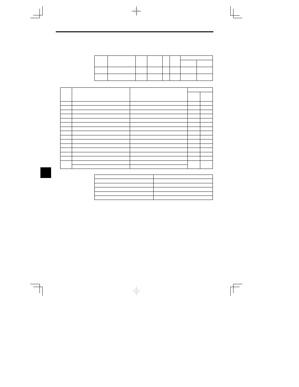
Multi-function Analog Input/Frequency Reference (Current): H3-05, H3-09
Constant Settings
User
Change
during
Setting
Factory
Valid Access Levels
User
Constant
Number
Name
during
Opera-
tion
Setting
Range
Unit
Factory
Setting
Open Loop
Vector
Flux Vector
H3-05
Multi-function analog
input (terminal 16)
0 to 1F
--
0
B
B
H3-09
Multi-function analog
input (terminal 14)
0 to 1F
--
1F
A
A
Table
7.8
Multi-function Input/Frequency Reference (Voltage) Function
Control Method
Setting
Function
Equivalent of 100% Input (10 V or 20 mA)
Open-
loop
Vector
Flux
Vector
0
Auxiliary frequency reference (H3-05)
Maximum output frequency
1
Frequency gain
Frequency reference (voltage) command value
2
Frequency bias
Maximum output frequency (added to H3-03)
5
Accel/Decel change (reduction coefficient)
Accel/Decel times (C1-01 to C1-08)
6
DC injection braking current
Inverter rated output current
7
Overtorque detection level
Motor rated torque
9
Frequency reference lower limit level
Maximum output frequency
A
Jump frequency
Maximum output frequency
10
Forward side torque limit
Motor rated torque
11
Reverse side torque limit
Motor rated torque
12
Regeneration for torque limit
Motor rated torque
13
Torque reference/torque limit for speed control
Motor rated torque
14
Torque compensation bias
Motor rated torque
15
Forward/reverse torque limit
Motor rated torque
1F
Disable analog input (H3-05)
----
1F
Frequency Reference (H3-09)
Maximum output frequency
D
The analog input signal level, gain, and bias are set with the following constants.
Terminal 16 signal level selector
H3-04 (0 to +10 V or 0 to
r10 V)
Terminal 16 input gain
H3-06
Terminal 16 input bias
H3-07
Terminal 14 signal level selector
H3-08 (0 to +10 V, 0 to
r10 V, or 4 to 20 mA)
Terminal 14 input gain
H3-10
Terminal 14 input bias
H3-11
D
When a voltage input is being input to terminal 14, be sure to disconnect jumper wire J1 on the control
PC board.
D
The input resistance will be destroyed if a voltage input is used without disconnecting the jumper wire.
D
Set the time constant in constant H3-12 when adding a primary delay filter to an analog input. This
filter time constant applies to all three of the analog inputs.
D
Settings 2 and D cannot be set at the same time. OPE07 will be detected.
7