Yaskawa VS-626 MC5 User Manual
Page 80
4.2Modes
- 17
User
Change
during
Setting
Factory
Valid Access Levels
User
Constant
Number
Name
during
Opera-
tion
Setting
Range
Unit
Factory
Setting
Open Loop
Vector
Flux Vector
o1-02
Monitor selection after
power up
1 to 4
--
1
B
B
Use constant o1-02 to indicate which value will be displayed when the Inverter is started. Refer to the fol-
lowing table.
Monitor Display Contents at Startup
Setting
Contents
1
Indicates the frequency reference at startup.
2
Indicates the output frequency at startup.
3
Indicates the output current at startup.
4
Indicates the value set in user constant o1-01 at startup.
Changing Monitor Display to Output Power at Startup in Basic Access Level
Change the access level to Basic if it is not already set there. Refer to Figure 4.4 for the procedure to change
from the Quick-start to Basic access level.
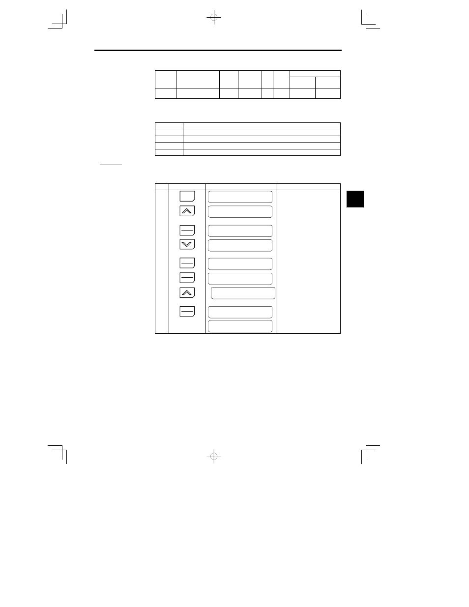
Use the following procedure to change the display from the output voltage to the output power.
Step
Key Sequence
Digital Operator Display
Remarks
1
MENU
MC5
Main Menu
Operation
2
Press twice.
MC5
Main Menu
Programming
3
DATA
ENTER
Function b1
Sequence
Changed to constant reading (func-
tion) level.
4
Press twice.
Function o1
Monitor Select
5
DATA
ENTER
User Monitor Sel
Output Voltage
Changed to constant setting level.
6
DATA
ENTER
o1
--
01 = 6
Output Voltage
7
Press twice.
o1
--
01 = 8
Output kWatts
8
DATA
ENTER
Entry Accepted
Writes-in the new setting.
User Monitor Sel
Output kWatts
After a few seconds, the Operator dis-
play is as shown on the left.
Output power has been set in place of output voltage.
4
A
EXAMPLE
"