Pg-x2 (for flux vector control mode only) – Yaskawa VS-626 MC5 User Manual
Page 60
3.7
Installing and Wiring PG Speed Control Cards
- 27
J
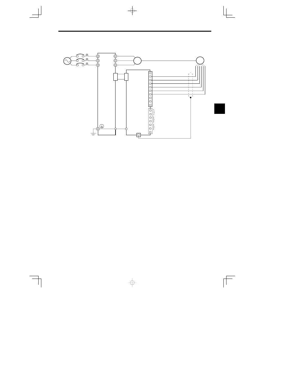
PG-X2 (For Flux Vector Control Mode Only)
IM
PG-X2
4CN
Power supply +12 V
Power supply 0 V
B-phase pulse monitor output
TA2
E
TA3 (E)
1
TA1
A-phase pulse monitor output
A-phase pulse input (--)
A-phase pulse input (+)
B-phase pulse input (--)
Z-phase pulse monitor output
9
10
B-phase pulse input (+)
Power supply +5 V
Three-phase 200 VAC
(400 VAC)
4CN
12
R
S
T
U
V
W
VS-626MC5
2
3
4
5
6
7
8
1
2
3
4
5
6
7
D
Shielded, twisted-pair wire must be used for signal lines.
D
Do not use the pulse generator’s power supply for anything other than the
pulse generator (encoder). Using it for another purpose can cause
malfunctions due to noise.
D
The length of the pulse generator’s wiring must not be more than 100 meters.
D
The direction of rotation of the PC can be set in user constant F1-05. The
factory preset if for forward rotation, A-phase advancement.
PG
Fig
3.25
PG-X2 Wiring
3