Yaskawa VS-626 MC5 User Manual
Page 49
Wiring
3.4.5 Wiring the Main Circuits
- 16
Countermeasures Against Radio Interference
Radio noise is generated from the Inverter as well as from the input and output lines. To reduce radio noise,
install noise filters on both input and output sides, and also install the Inverter in a totally enclosed steel
box.
The cable between the Inverter and the motor should be as short as possible.
Steel box
IM
Noise
filter
Noise
filter
Metal pipe
Power
supply
MCCB
VS-626MC
5
Fig
3.12
Countermeasures Against Radio Interference
Cable Length between Inverter and Motor
If the cable between the Inverter and the motor is long, the high-frequency leakage current will increase,
causing the Inverter output current to increase as well. This may affect peripheral devices. To prevent this,
adjust the carrier frequency (set in C6-01) as shown in Table 3.6. (For details, refer to the user constant
settings.)
Table
3.6
Cable Length between Inverter and Motor
Cable length
50 m max.
100 m max.
More than 100 m
Carrier frequency
15 kHz max.
10 kHz max.
5 kHz max.
(Set value
:
C6-01)
(15.0)
(10.0)
(5.0)
J
Ground Wiring
D
Always use the ground terminal of the 200 V Inverter with a ground resistance of less than 100
: and
that of the 400 V Inverter with a ground resistance of less than 10
:.
D
Do not share the ground wire with other devices, such as welding machines or power tools.
D
Always use a ground wire that complies with technical standards on electrical equipment and mini-
mize the length of the ground wire.
Leakage current flows through the Inverter. Therefore, if the distance between the ground electrode
and the ground terminal is too long, potential on the ground terminal of the Inverter will become unsta-
ble.
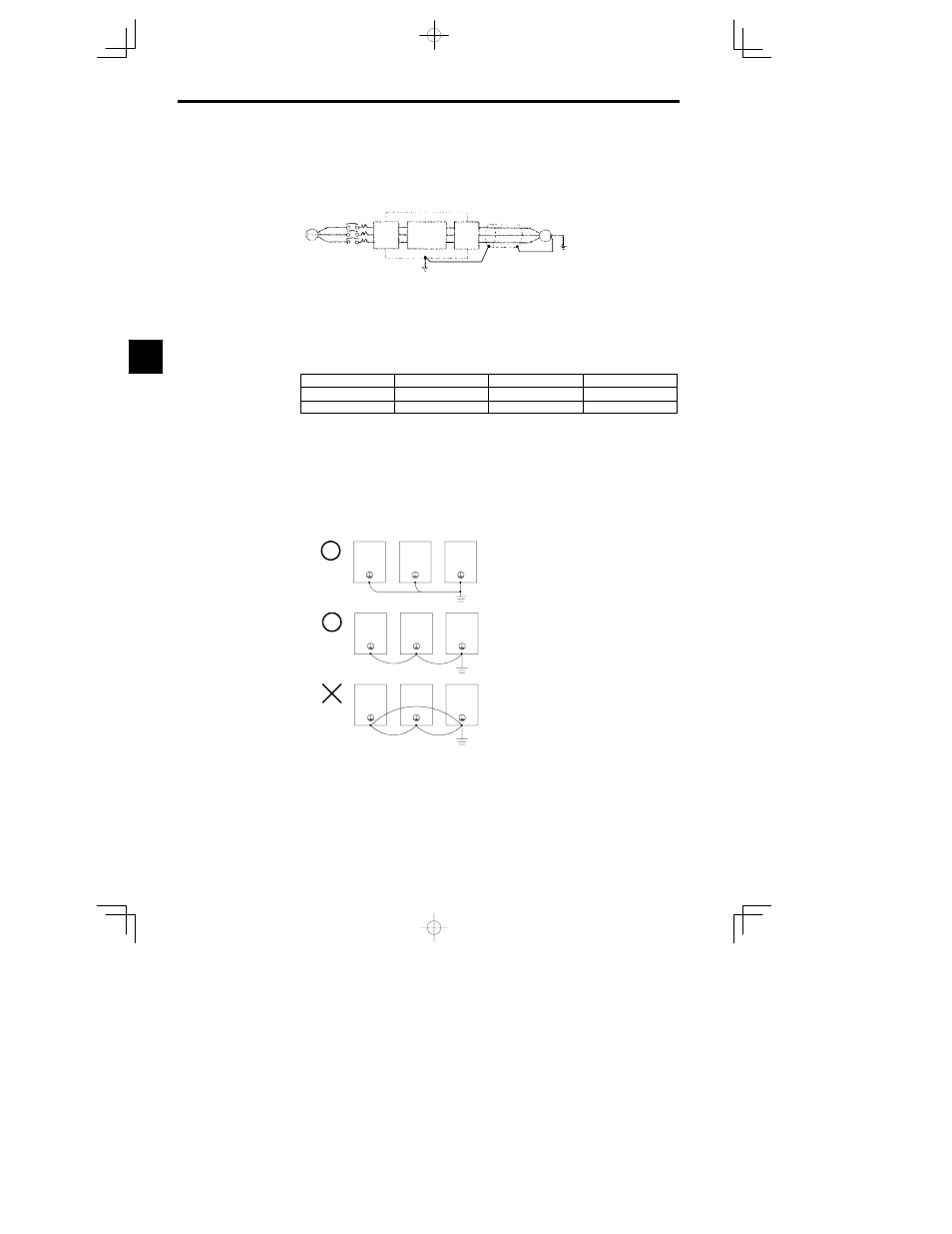
D
When using more than one Inverter, be careful not to loop the ground wire.
OK
OK
NO!
Fig
3.13
Ground Wiring
3