Yaskawa VS-626 MC5 User Manual
Page 191
7.3
Common Functions
- 53
Stall Prevention Selection During Decel: L3-04
User
Change
during
Setting
Factory
Valid Access Levels
User
Constant
Number
Name
during
Opera-
tion
Setting
Range
Unit
Factory
Setting
Open Loop
Vector
Flux Vector
L3-04
Stall prevention selec-
tion during decel
0 to 3
--
1
B
B
D
Settings
Setting
Function
0
Disabled. (Decelerate according to the settings. Main circuit overvoltage may occur if the decel-
eration time is too short.)
1
Enabled. (Stops deceleration if the main circuit voltage exceeds the overvoltage level. Decelerate
again when voltage recovers.)
2
Optimum deceleration. (Decelerate as fast as possible judging from the main circuit voltage.
Disregard the deceleration time setting.)
3
Enabled (with braking resistor)
D
When setting 1 (enabled) is selected, the deceleration time is extended automatically so that a main
circuit overvoltage doesn’t occur.
D
Always select setting 0 or 3 when a braking option (Braking Resistor, Braking Resistor Unit, or Brak-
ing Unit) is being used. If setting 1 or 2 is selected, the braking option won’t be used and the decelera-
tion time can’t be shortened.
D
L3--04 cannot be set to 2 for open--loop vector control mode. (Settings can be made for SPEC: F and
later)
D
L3-04 = 3 cannot be set to 2 for vector control modes.
Settings: Differences Between 0 and 3
D
When set to 0, the stall prevention cannot be used when decelerating.
D
When set to 3, disabled if over voltage (OV) occurs often in the main circuit, the deceleration time is
automatically extended slightly. In other cases, deceleration occurs within the specified deceleration
time. The actual deceleration time may be longer than the specified deceleration time, but a decelera-
tion time that is lower than that when set to 0 is also possible.
When the setting for stall prevention during deceleration is set to 3, be sure to make adjustments ac-
cording to the following procedure:
Adjusting the Settings
1. Set the deceleration time according to the braking power and machine inertia.
2. When the braking power or the machine inertia is unknown, set L3--04 to 0 and do a trial run to deter-
mine the minimum deceleration time. Then set L3--04 to 3.
3. Lower the (setting for the) deceleration time to a value in the range where main circuit overvoltages
(OV) will not occur.
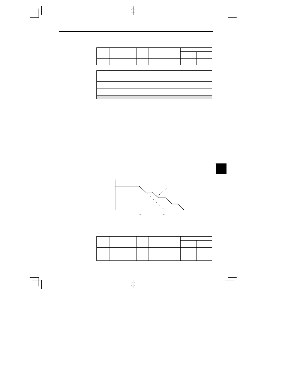
The deceleration time is controlled
to prevent overvoltage.
Output frequency
Time
Deceleration time
(setting)
Fig
7.32
Deceleration Stall Prevention Function: L3-04 = 1
J
Frequency Detection Settings: L4-01 to L4-05
User
Change
during
Setting
Factory
Valid Access Levels
User
Constant
Number
Name
during
Opera-
tion
Setting
Range
Unit
Factory
Setting
Open Loop
Vector
Flux Vector
L4-01
Speed agree detection
level
0.0 to 400.0
Hz
0.0
B
B
L4-02
Speed agree detection
width
0.0 to 20.0
Hz
2.0
B
B
7