2 specifications of options and peripheral devices – Yaskawa VS-626 MC5 User Manual
Page 267
Specifications
- 6
11.2 Specifications of Options and Peripheral Devices
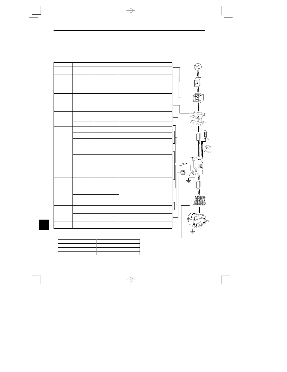
The following options and peripheral devices can be used for the VS-626MC5. Select them according to the
application.
Table
11.3
Options and Peripheral Devices
Purpose
Name
Model (Code)
Descriptions
Protect Invert-
er wiring
MCCB or Ground
Fault Interrupter
NF
*1
Always connect a breaker to the power supply line to pro-
tect Inverter wiring. Use a ground fault interrupter suitable
for high frequencies.
Prevents burn-
ing when a
Braking Resis-
tor is used.
Magnetic Contactor
HI- E
Install to prevent the braking resistor from burning out
when one is used. Always attach a surge absorber to the
coil.
Contains
switching
surge
Surge Absorber
DCR2-
Absorbs surge from the magnetic contactor and control
relays. Connect surge absorbers to all magnetic contactors
and relays near the Inverter.
Isolates I/O
signals
Isolator
DGP
Isolates the I/O signals of the Inverter and is effective
against inductive noise.
Improve the in-
put power fac-
tor of the In-
verter
DC Reactor
AC Reactor
UZDA-
UZBA-
Used to improve the input power factor of the Inverter. All
VS-626MC5 Inverters of 18.5 kW or higher contain built-in
DC reactors. These are optional for Inverters of 15 kW or
less. Install DC and AC reactors for applications with a
large power supply capacity (600 kVA or higher).
Reduce the af-
fects of radio
and control de-
Input Noise Filter
Single-phase: LNFB-
3-phase: LNFD- HF
Reduces noise coming into the inverter from the power
supply line and to reduce noise flowing from the inverter
into the power supply line. Connect as close to the Inverter
as possible.
and control de-
vice noise
Output Noise Filter
LF-
Reduces noise generated by the Inverter. Connect as close
to the Inverter as possible.
Enable stop-
Braking Resistor
ERF-150WJ
(R00
)
Consumes the regenerative motor energy with a resistor to
reduce deceleration time (use rate: 3% ED).
Enable stop
ping the ma-
chine in a set
time
Braking Resistor
Unit
LKEB-
(75600-K
0)
Consumes the regenerative motor energy with a resistor to
reduce deceleration time (use rate: 10% ED).
time
Braking Unit
CDBR-
(72600-R
0)
Used with a Braking Resistor Unit to reduce the decelera-
tion time of the motor.
Operates the
VS Operator
*
2
(small plastic Oper-
ator)
JVOP-95
(73041-0905X- )
Allows frequency reference settings and ON/OFF operation
control to be performed by analog references from a remote
location (50 m max.).
Frequency counter specifications: 60/120 Hz, 90/180Hz
Operates the
Inverter exter-
nally
VS Operator
(Standard steel-
plate Operator)
JVOP-96
(73041-0906X- )
Allows frequency reference settings and ON/OFF operation
control to be performed by analog references from a remote
location (50 m max.).
Frequency counter specifications: 75 Hz, 150 Hz, 220 Hz
Digital Operator
Connection Cable
1 m cable: (72616-W5001)
3 m cable: (72616-W5003)
Extension cable to use a Digital Operator remotely.
Cable length: 1 m or 3 m
Controls an In-
verter system
VS System Module
JGSM-
A system controller that can be match to the automatic con-
trol system to produce an optimum system configuration.
Provides In-
verter momen-
tary power loss
recovery time
Momentary Power
Loss Recovery Unit
P00 0
(73600-P00 0)
Handles momentary power losses for the control power
supply (maintains power for 2 s).
Frequency Meter
DCF-6A
Set/monitor
Frequency Setter
RV30YN20S (2 k )
Devices to set or monitor frequencies externally.
Set/monitor
frequencies
and voltages
externally
Frequency Setter
Knob
CM-3S
Devices to set or monitor frequencies externally.
g
externally.
Output Voltmeter
SCF-12NH
Measures the output voltage externally and designed for use
with a PWM Inverter.
Correct fre-
quency refer-
ence input, fre-
Variable Resistor
Board for Frequen-
cy Reference
2 k : (ETX003270)
20 k: (ETX003120)
Connected to the control circuit terminals to input a fre-
quency reference.
ence input, fre
quency meter,
ammeter
scales
Frequency Meter
Scale Correction
Resistor
RH000850
Calibrates the scale of frequency meters and ammeters.
Performs wind-
ing change
Magnetic contactor
for winding
selection
HV-75AP3
HV-150AP3
Install to perform winding change.
* 1. Use a ground fault interrupter with a current sensitivity of 200 mA minimum and an operating time of 0.1 s minimum to prevent
operating errors. The interrupter must be suitable for high-frequency operation.
* 2. The suffixes of the model and code numbers of VS Operators indicate frequency meters are shown in the following table.
Model No.
Code No.
Frequency Meter Specifications
JVOP-95 1
73041-0905X-01
TRM-45 3 V 1 mA 60/120 Hz
JVOP-95 2
73041-0905X-02
TRM-45 3 V 1 mA 90/180 Hz
JVOP-96 1
73041-0906X-01
DCF-6A 3 V 1 mA 75 Hz
11
Power supply
MCCB or
ground fault
interrupter
Magnetic
contactor
AC reactor to im-
prove power factor
Braking
resistor
Input-line noise
filter
VS-626MC5
DC reactor
to improve
power factor
Ground
Output-line
noise filter
Motor
Ground
626MC5
Magnetic
contactor