3 common functions – Yaskawa VS-626 MC5 User Manual
Page 155
7.3
Common Functions
- 17
7.3
Common Functions
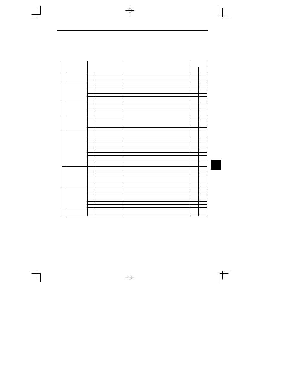
The functions that can be used for all control methods are listed in Table 7.3. Details on functions marked with
a
are provided in the following table.
Table
7.3
Functions Used with All Control Methods
Group
Function
Comments
Control Meth-
od
Group
Function
Comments
Open
Loop
Vector
Flux
Vector
b1
Sequence
Settings such as the reference input method
b
Application
b2
DC Injection Braking
DC injection braking function settings
b
Application
b3
Speed Search
Speed search function settings
C1
Accel/Decel
Acceleration/deceleration time settings
C2
S-Curve Acc/Dec
S-curve characteristics for acceleration/deceleration times
C3
Motor-Slip Compensation
Slip compensation function settings
C Tuning
C4
Torque Compensation
Torque compensation function settings
C Tuning
C5
Speed Controls
Speed control tuning
C6
Carrier Frequency
Carrier frequency settings
C8
Factory Tuning
Adjustment for open-loop vector control
d1
Preset Reference
Frequency reference settings (when using Operator)
d2
Reference Limits
Frequency upper and lower limit settings
d
Reference
d3
Prohibited Frequencies
Prohibited frequency settings
d4
Reference Frequence Hold
Functions
Up/Down, Accel/Decel stop hold frequency setting
E1
V/f Pattern
Motor constant settings
E2
Motor Setup
Motor constant settings
E
Motor
E3
Motor 2 Control Methods
Control method settings for motor 2.
E
Motor
E4
Motor 2 V/f Characteristics
V/f characteristics settings for motor 2.
E5
Motor 2 Motor Constants
Motor constant setting for motor 2.
F1
PG Speed Control Card
Settings
Constant settings for a PG Speed Control Card
F2
Analog Reference Card AI
User constant settings for an Analog Reference Card
F3
Digital Reference Card DI
User constant settings for a Digital Reference Card
F4
Analog Monitor Card AO
User constant settings for an Analog Monitor Card
F
Options
F5
Digital Output Card DO
User constant settings for a Digital Output Card
F
Options
F6
Digital Output Card DO
User constant settings for a Digital Output Card
F7
Pulse Monitor Card PO
User constant settings for a Pulse Monitor Card
F8
SI-F/SI-G Transmission
Card
User constant settings for a Transmission Card
F9
CP-916B Transmission
Card
User constant settings for a Transmission Card
H1
Multi-function Inputs
Function selection for multi-function inputs
H2
Multi-function Outputs
Function selection for multi-function outputs
H T
i
l
H3
Analog Inputs
Function selection for analog inputs
H Terminal
H4
Multi-function Analog Out-
puts
Function selection for analog outputs
H5
MEMOBUS Communica-
tions
MEMOBUS communications settings
---
---
L1
Motor Overload
Sets electrical/thermal functions that protect the motor.
L2
Power Loss Ridethru
Selects the power-loss processing method.
L3
Stall Prevention
Accel/Decel stall prevention settings and selection
L
Protection
L4
Reference Detection
Frequency detection settings and selection
L
Protection
L5
Fault Restart
Fault restart function settings
L6
Torque Detection
Sets overtorque detection functions 1 and 2
L7
Torque Limit
Torque limit settings
L8
Hardware Protection
Hardware overheating and open-phase protection settings
o
Operator
o1
Monitor Select
Selects the Operator display and setting methods.
o
Operator
o2
Key Selections
Operator key function selection and other constants
7