Yaskawa VS-626 MC5 User Manual
Page 188
Advanced Operation
7.3.6 Protective Functions: L
- 50
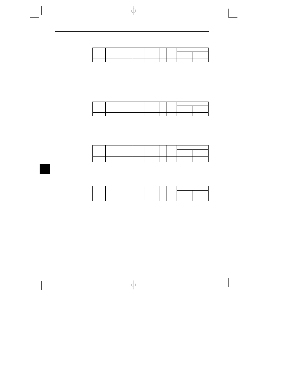
Minimum Baseblock Time: L2-03
User
Change
during
Setting
Factory
Valid Access Levels
User
Constant
Number
Name
during
Opera-
tion
Setting
Range
Unit
Factory
Setting
Open Loop
Vector
Flux Vector
L2-03
Min. baseblock time
0.0 to 5.0
s
0.5
B
B
D
The factory setting depends on the Inverter capacity. The factory setting shown in the table is for a 200
V class, 0.4 kW Inverter. (See page NO TAG.)
D
This setting is used with the speed search and DC injection braking functions.
D
Set the time required for the leakage voltage to dissipate. Increase the setting if an overcurrent (OC)
occurs when the speed search or DC injection braking function starts.
D
Set the baseblock time during winding change. Time for winding change varies according to the set-
ting. (For example, lower the setting, and time for winding change is also reduced.) Overcurrent (OC)
might occur if setting is too low.
D
This setting is valid for speed searches performed after a momentary power loss and regular speed
searches.
Voltage Recovery Time: L2-04
User
Change
during
Setting
Factory
Valid Access Levels
User
Constant
Number
Name
during
Opera-
tion
Setting
Range
Unit
Factory
Setting
Open Loop
Vector
Flux Vector
L2-04
Voltage recovery time
0.0 to 5.0
s
0.3
A
A
D
Set the time allowed for the normal voltage to be restored after completion of the speed search.
For a 200 V class Inverter, this is the time in seconds for voltage to be restored from 0 VAC to 200 VAC.
For a 400 V class Inverter, this is the time in seconds for voltage to be restored from 0 VAC to 400 VAC.
D
This setting is valid for speed searches after a momentary power loss, regular speed searches, the volt-
age changes with energy-saving control, and the voltage changes with baseblock clearing.
D
Set the voltage recovery time after baseblock during winding change. Ovrevoltage (OV) might occur
if setting is too low.
Undervoltage Detection Level: L2-05
User
Change
during
Setting
Factory
Valid Access Levels
User
Constant
Number
Name
during
Opera-
tion
Setting
Range
Unit
Factory
Setting
Open Loop
Vector
Flux Vector
L2-05
Undervoltage detection
level
150 to 210
(300 to 420) VDC
190
(380)
A
A
D
The values in parentheses are for 400 V class Inverters. (See page NO TAG.)
D
Normally it isn’t necessary to change this setting.
D
Use this constant when you want to add an AC reactor and lower the main circuit undervoltage detec-
tion level. Be sure to set a main circuit DC voltage value (V) that will detect a main circuit undervol-
tage.
KEB Deceleration Rate L2-06
User
Change
during
Setting
Factory
Valid Access Levels
User
Constant
Number
Name
during
Opera-
tion
Setting
Range
Unit
Factory
Setting
Open Loop
Vector
Flux Vector
L2-06
KEB deceleration rate
0.0 to 100.0
0.1
0.0
A
A
D
The KEB function restores the operating conditions for momentary power loss by applying a frequen-
cy deceleration to create inertia energy when a power loss occurs, and thus avoid the power loss.
D
This function is normally used with film lines and other applications where multiple Inverters are con-
nected to the main DC line. Synchronous deceleration for power loss prevents the line from stopping
as the result of speed fluctuations.
D
The KEB operation is performed using a KEB command (setting of 65 or 66) for a multi-function in-
put.
D
Applicable Capacities
200 V class Inverters: 0.4 to 15 kW
400 V class Inverters: 0.4 to 18.5 kW
7