Yaskawa VS-626 MC5 User Manual
Page 41
Wiring
3.4.1 Applicable Wire Sizes and Closed-loop Connectors
- 8
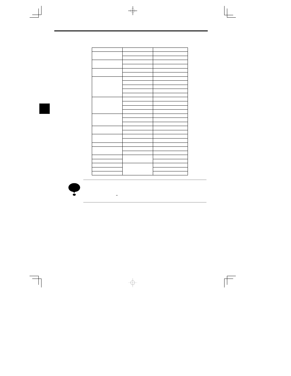
Table
3.3
Closed-loop Connector Sizes (JIS C 2805) (For 200 V/400 V Classes)
Wire Thickness mm
2
Terminal Screws
Size
0 5
M3.5
1.25 to 3.5
0.5
M4
1.25 to 4
0 75
M3.5
1.25 to 3.5
0.75
M4
1.25 to 4
1 25
M3.5
1.25 to 3.5
1.25
M4
1.25 to 4
M3.5
2 to 3.5
M4
2 to 4
2
M5
2 to 5
M6
2 to 6
M8
2 to 8
M4
5.5 to 4
3 5/5 5
M5
5.5 to 5
3.5/5.5
M6
5.5 to 6
M8
5.5 to 8
M5
8 to 5
8
M6
8 to 6
M8
8 to 8
14
M6
14 to 6
14
M8
14 to 8
22
M6
22 to 6
22
M8
22 to 8
30/38
M8
38 to 8
50/60
M8
60 to 8
50/60
M10
60 to 10
80
M10
80 to 10
100
M10
100 to 10
100
100 to 12
150
M12
150 to 12
200
200 to 12
Determine the wire size for the main circuit so that line voltage drop is within 2% of the rated voltage.
Line voltage drop is calculated as follows:
(If there is the possibility of excessive voltage drop, use a larger wire suitable to the required length.)
Line voltage drop (V)
3
¯ x wire resistance (:/km) x wire length (m) x current (A) x 10
--3
3
NOTE