Yaskawa VS-626 MC5 User Manual
Page 62
3.7
Installing and Wiring PG Speed Control Cards
- 29
J
Closed-loop Connector Sizes and Tightening Torque
The closed-loop connectors and tightening torques for various wire sizes are shown in Table 3.14.
Table
3.14
Closed-loop Connectors and Tightening Torques
Wire Thickness [mm
2
]
Terminal
Screws
Crimp Terminal Size
Tightening Torque (N m)
0.5
1.25 to 3.5
0.75
M3 5
1.25 to 3.5
0 8
1.25
M3.5
1.25 to 3.5
0.8
2
2 to 3.5
J
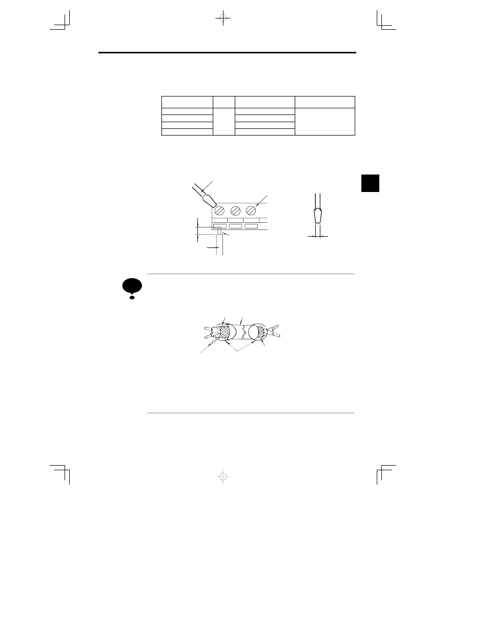
Wiring Method
Use the following procedure to connect wires to the terminal block.
1. Loosen the terminal screws with a thin-slot screwdriver.
2. Insert the wires from underneath the terminal block.
3. Tighten the terminal screws firmly.
Thin-slot screwdriver
Strip the end for
5.5 mm if no
solderless ter-
minal is used.
Solderless terminal or
wire without soldering
Control circuit
terminal block
Wires
3.5 mm max.
Blade thickness
:
0.6 mm max.
Blade of screwdriver
Fig
3.27
Connecting Wires to Terminal Block
Wiring Precautions
1.
Separate PG Speed Control Card control circuit wiring (terminals TA1 and TA2) from main circuit wiring
and other high-power lines.
2. Use twisted-pair or shielded twisted-pair cables to connect the PG to prevent operating faults. Process
cable ends as shown in Figure 3.28. The maximum cable length is 100 m.
Do not connect here.
Connect to terminal
TA3 on the
VS-626MC5.
Shield sheath
Armor
Insulate with tape.
Fig
3.28
Processing the Ends of Twisted-pair Cables
3. Connect the shield to the ground terminal.
4. Do not solder the wires to the control circuit terminals. The wires may not contact well with the control
circuit terminals if the wires are soldered.
5. The end of each wire connected to the control circuit terminals must be stripped for approximately
5.5 mm.
3
NOTE