Yaskawa VS-626 MC5 User Manual
Page 58
3.7
Installing and Wiring PG Speed Control Cards
- 25
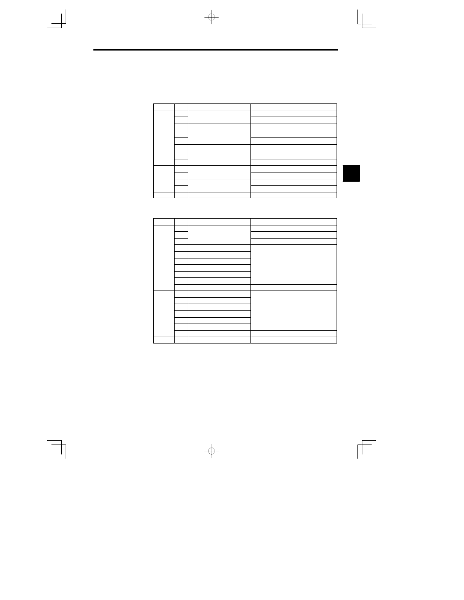
3.7.2 PG Speed Control Card Terminal Blocks
The terminal specifications for each PG Speed Control Card are given in the following tables.
J
PG-B2 (For Flux Vector Control Mode Only)
Table
3.10
PG-B2 Terminal Specifications
Terminal
No.
Contents
Specifications
1
Power supply for pulse generator
12 VDC (
r5%), 200 mA max.
2
Power supply for pulse generator
0 VDC (GND for power supply)
TA1
3
A-phase pulse input terminal
H: +8 to 12 V
L: +1 V max.
(Maximum response frequency: 30 kHz)
TA1
4
Pulse input common
5
B-phase pulse input terminal
H: +8 to 12 V
L: +1 V max.
(Maximum response frequency: 30 kHz)
6
Pulse input common
1
A phase monitor output terminal
Open collector output, 24 VDC, 30 mA max.
TA2
2
A-phase monitor output terminal
A-phase monitor output common
TA2
3
B phase monitor output terminal
Open collector output, 24 VDC, 30 mA max.
4
B-phase monitor output terminal
B-phase monitor output common
TA3
(E)
Shield connection terminal
J
PG-X2 (For Flux Vector Control Mode Only)
Table
3.11
PG-X2 Terminal Specifications
Terminal
No.
Contents
Specifications
1
12 VDC (
r5%), 200 mA max. (see note)
2
Power supply for pulse generator
0 VDC (GND for power supply)
3
pp y
p
g
5 VDC (
r5%), 200 mA max. (see note)
4
A-phase + input terminal
TA1
5
A-phase -- input terminal
TA1
6
B-phase + input terminal
Line driver input (RS-422 level input)
7
B-phase -- input terminal
Line driver input (RS-422 level input)
Maximum response frequency: 300 kHz
8
Z-phase + input terminal
9
Z-phase -- input terminal
10
Common terminal
0 VDC (GND for power supply)
1
A-phase + output terminal
2
A-phase -- output terminal
3
B-phase + output terminal
Line driver output (RS 422 level output)
TA2
4
B-phase -- output terminal
Line driver output (RS-422 level output)
5
Z-phase + output terminal
6
Z-phase -- output terminal
7
Control circuit common
Control circuit GND
TA3
(E)
Shield connection terminal
Note 5 VDC and 12 VDC cannot be used at the same time.
3