400 v class – Yaskawa VS-626 MC5 User Manual
Page 44
3.4
Wiring Main Circuit Terminals
- 11
J
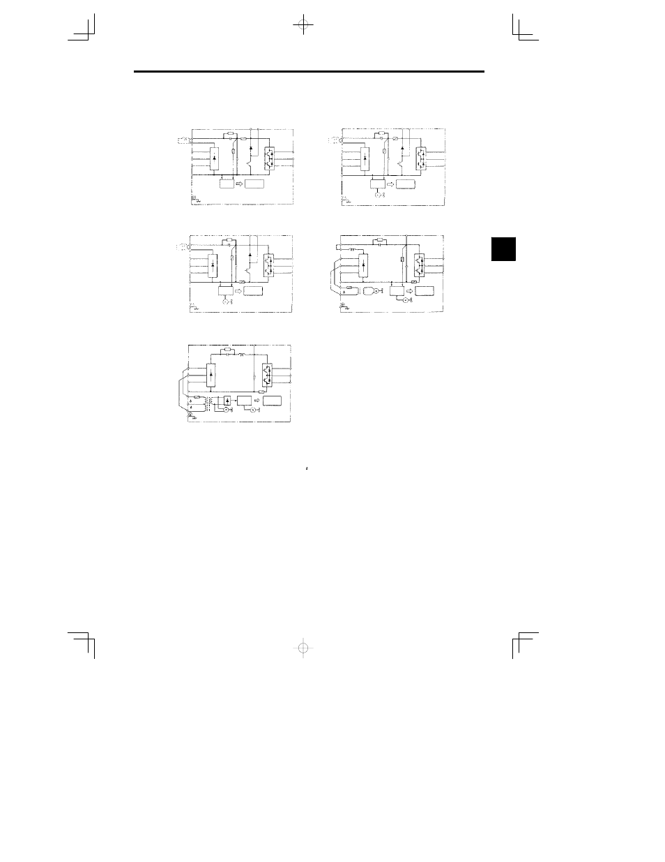
400 V Class
CIMR-MC5A40P4 to 41P5 0.4 to 1.5 kW
CIMR-MC5A4018 to 4045 18.5 to 45 kW
CIMR-MC5A42P2 to 43P7 2.2 3.7 kW
CIMR-MC5A4055 to 4075 55 75 kW
(DCL
option)
V(T2)
W(T3)
U(T1)
B2
B1
©
T(L3)
S(L2)
¨
2
¨
1
R(L1)
V(T2)
W(T3)
U(T1)
B2
B1
©
T(L3)
S(L2)
¨
2
¨
1
R(L1)
(DCL
option)
*
2
*
1
*
2
*
1
V
W
U
©
T
S
¨
2
¨
1
R
V
W
U
©
T
S
R
r
¨
3
r
200
400
¨
3
*
1
*
1
*
3
CIMR-MC5A45P5 to 4015 5.5 to 15 kW
V(T2)
W(T3)
U(T1)
B2
B1
©
T(L3)
S(L2)
¨
2
¨
1
R(L1)
(DCL
option)
*
2
*
1
Power
supply
(RCC)
Control
circuits
Power
supply
(RCC)
Control
circuits
Fin cooling fan
Power
supply
(RCC)
Control
circuits
Fin cooling fan
Power
supply
(RCC)
Control
circuits
Fin cooling fan
Internal
cooling fan
Power
supply
(RCC)
Fin cooling fan
Internal
cooling fan
Control
circuits
*
1 Prewired at the factory.
*
2 Remove the short-circuit bar from between
¨
1 and
¨
2 when connecting a DC
reactor to Inverters of 15 kW or less.
*
3 Prewired at the factory. When supplying power to the main circuits from the DC
power supply, remove the wiring from R-r and S- .
Fig
3.5
400 V Class Inverter Main Circuit Configurations
3