Wire sizes and distances – Yaskawa VS-626 MC5 User Manual
Page 276
12.3
Peripheral Device Application Precautions
- 7
J
Wire Sizes and Distances
Motor torque will be reduced by voltage drop along the cable if the distance between the Inverter and the
motor is too long. This is particularly noticeable for low-frequency outputs. Use wires of sufficient size.
Always use the optional extension cables when operating the Digital Operator separated from the Inverter.
For remote operation using analog signals, keep the control line length between the Analog Operator or op-
eration signals and the Inverter to 50 m or less, and separate the lines from high-power lines (main circuits
or relay sequence circuits) to reduce induction from peripheral devices.
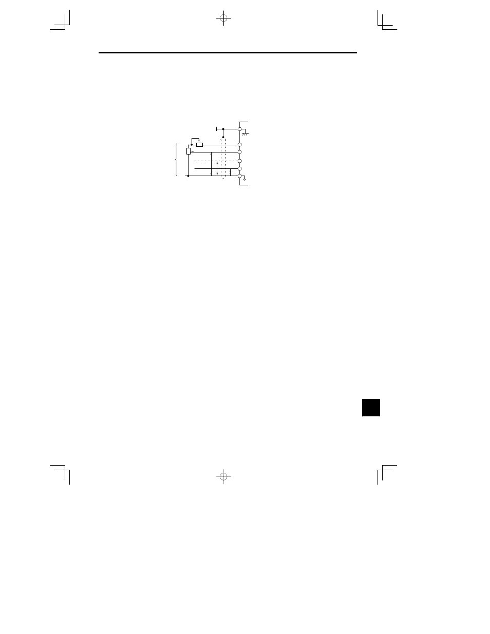
When setting frequencies from an external frequency setter (and not from a Digital Operator), used shielded
twisted-pair wires and ground the shield to terminal 12, as shown in the following diagram.
0 V
17
Multi-function analog input
0 to 10 V (20 k )
16
Master speed reference
4 to 20 mA (250 )
14
Master speed reference
0 to 10 V (20 k )
13
Speed setting power supply
+15 V 20 mA
15
Shield terminal
12
2k
3
2
1
0 to +10 V
P
4 to 20 mA
0 to +10 V
0 V
External
frequency
reference
2 k
P
P
12