Yaskawa VS-626 MC5 User Manual
Page 172
Advanced Operation
7.3.5 External Terminal Functions: H
- 34
D
With this setting, a temperature sensor can be connected to the multi-function input to display a warn-
ing message when the temperature rises too high.
Multi-function Analog Input Selection (Setting: C)
OFF
Disables the multi-function analog input (terminal 16).
ON
Enables the multi-function analog input (terminal 16).
D
With this setting, the multi-function input can be used to enable or disable the multi-function analog
input.
D
Turning the input OFF has the same effect as setting H3-05 (the multi-function analog input selector
for terminal 16) to 1F.
Speed Control Integral Reset (Setting: E)
OFF
Operates with PI-control speed control loop.
ON
Operates with P-control speed control loop. (The speed control integral values are reset by the
integral time constant.)
D
It is possible to switch between these speed control modes during operation.
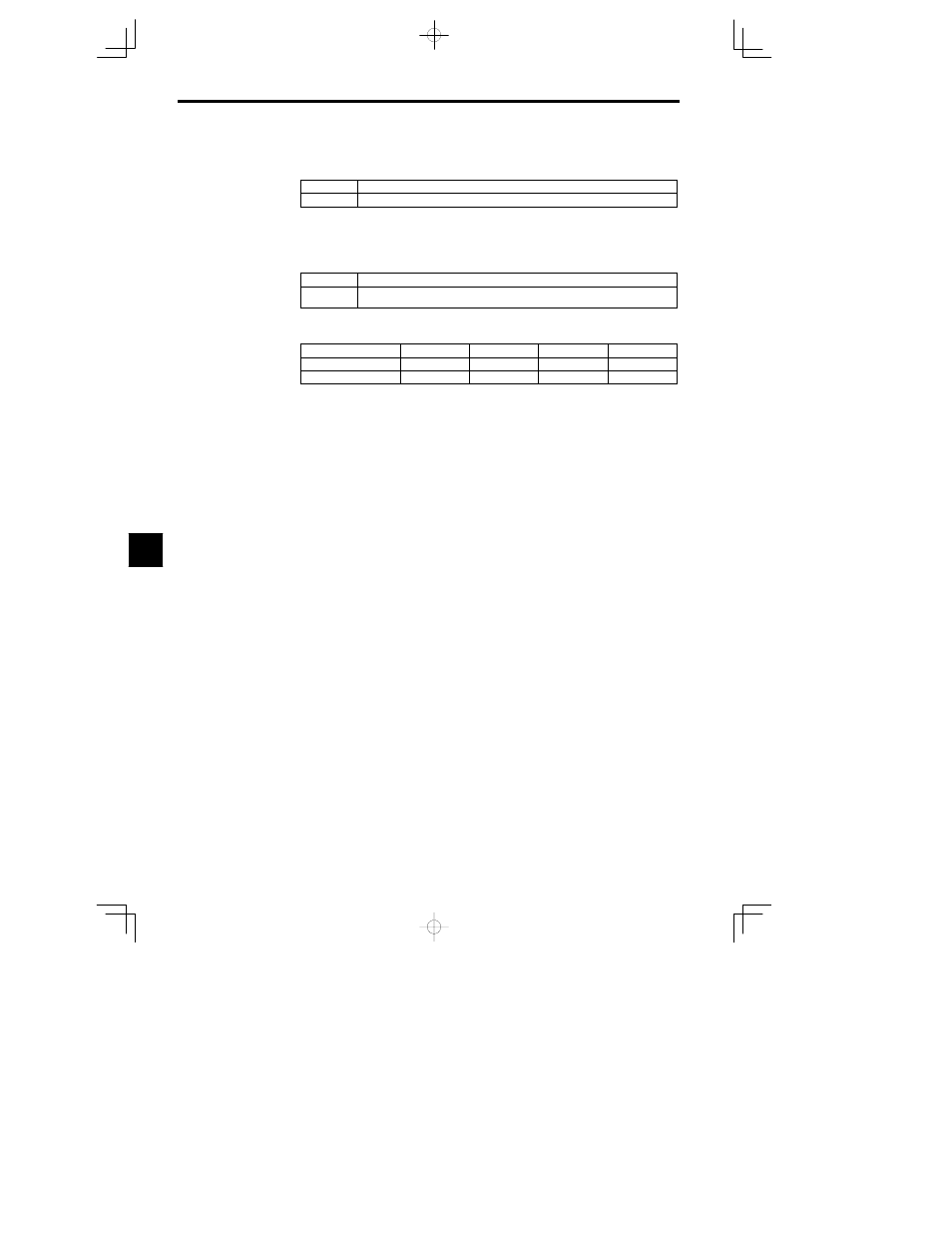
Up and Down Commands (Settings: 10 and 11)
Up command
ON
OFF
ON
OFF
Down command
OFF
ON
ON
OFF
Operation
Acceleration
Deceleration
Hold
Hold
D
With these settings, the multi-function inputs can be used to control the Inverter’s output frequency.
D
When using this function, be sure to set both the up command (setting 10) and the down command
(setting 11) for 2 multi-function inputs. An OPE03 option fault will occur if only one of these com-
mands is set or if an acceleration/deceleration ramp hold input (setting A) is set at the same time.
D
Be sure to set constant b1-02 (the run command source selector) to 1 (external terminal). The up/down
function won’t operate with any other b1-02 setting.
D
The frequency up/down commands operate according to the normal acceleration/deceleration times
in C1-01 to C1-08.
D
The upper and lower limits for the output frequency with the up/down commands are determined by
the following settings:
x
Upper limit = Maximum output frequency (E1-04)
Reference upper limit (d2-01) 100
x
Lower limit = Maximum output frequency (E1-04)
Reference lower limit (d2-02) 100
D
When frequency reference (voltage) terminal 13 or frequency reference (current) terminal 14 is being
used as a frequency reference input, the greatest frequency value becomes the lower limit.
D
When the up/down function is being used, the output frequency will be accelerated to the lower limit
if a run command is input.
D
When the up/down function and jog frequency reference are both assigned to multi-function inputs,
an ON jog frequency reference input has the highest priority.
D
Multi-step speed references 1 to 8 are all disabled when the up/down function has been set.
D
The output frequency held by the up/down function will be stored in memory if d4-01 (the frequency
reference hold function selector) is set to 1. This output frequency will be retained even after a power
loss, and operation will be restarted at this frequency the next time that a run command is input. The
stored output frequency will be cleared from memory if the up or down command is turned ON while
the run command is OFF (see “Reference frequency reset” in Figure 7.19) .
7