Yaskawa VS-626 MC5 User Manual
Page 174
Advanced Operation
7.3.5 External Terminal Functions: H
- 36
x
The control method, V/f characteristics, and motor constants recorded in the Inverter can be
switched by setting “16” (motor switch command) for a constant from H1-01 to 06 (multi-function
inputs), and then inputting a signal while the motor is stopped.
x
The current motor selection can be monitored at a multi-function output terminal by setting “1C”
(motor selection monitor) for a constant from H2-01 to 03 (multi-function outputs).
x
Set the Basic (3) or Advanced (4) access level in the initialize setting A1-01 (access level).
x
The constants being used will changed as shown in the following table for the motor switch com-
mand.
Motor Switch command
OPEN (motor 1)
CLOSED (motor 2)
Control method
A1-02 (control method in initialize
settings)
E3-01 (motor 2 control method)
V/f characteristics
E1-04 to 13 (V/f characteristics)
E4-01 to 07
(
motor 2 V/f character-
istics)
Motor constants
E2-01 to 09 (motor constants)
E5-01 to 06 (motor 2 motor
constants)
Motor selection monitor
OPEN
CLOSED
D
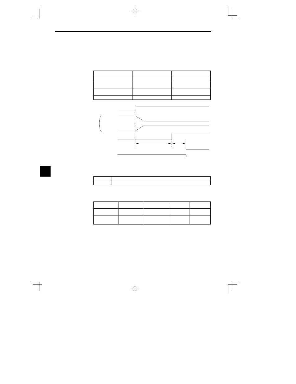
The timing chart for switching between motor 1 and motor 2 is shown below.
Turn ON the Forward (reverse) command only
after confirming the status of the motor selection
monitor.
Motor switching
contactor
Motor switch command
M1 operation
M2 operation
Motor selection monitor
Forward (reverse)
command
OFF
ON
Approx.
200
ms
Approx.
50
ms
OFF
ON
OFF
ON
OFF
ON
OFF
ON
(Approx. 500 ms for control with a PG)
Fig
7.20
Timing Chart for Switching from Motor 1 to Motor 2
Constants Write Enable (Setting: 1B)
OFF
Write-protects all constants except for frequency monitor.
ON
Allows constants specified in Initialize mode to be changed.
D
With this setting, the multi-function input can be used to write-protect the Operator constants. When
the input is OFF, the Operation mode frequency can be monitored and the frequency can be changed
but other changes are prohibited.
Trim Control Increase and Decrease (Settings: 1C and 1D)
Trim Control In-
crease
ON
OFF
ON
OFF
Trim Control De-
crease
OFF
ON
ON
OFF
Output frequency
Reference frequency
+ trim control level
(d4-02)
Reference frequency --
trim control level
(d4-02)
Reference fre-
quency
Reference fre-
quency
D
The trim control increase function adds the level in d4-02 to the analog frequency reference.
D
The trim control decrease function subtracts the level in d4-02 to the analog frequency reference.
D
These functions are effective when the frequency reference is input from an analog input. These func-
tions must both be set at the same time or an OPE03 fault will occur. The analog frequency reference
won’t be changed when both the trim control increase and decrease inputs are ON. The output frequen-
cy will be zero when the trim control decrease input is ON and the result of the subtraction is less than
zero.
Analog Frequency Reference Sample/Hold (Setting: 1E)
D
The analog input value will become the frequency reference 100 ms after the multi-function input
closes.
7