Yaskawa VS-626 MC5 User Manual
Page 48
3.4
Wiring Main Circuit Terminals
- 15
J
Wiring on the Output Side of Main Circuit
Connecting the Inverter and Motor
Connect output terminals U, V, and W to motor lead wires U, V, and W, respectively.
Check that the motor rotates forward with the forward run command. Switch over any two of the output
terminals to each other and reconnect if the motor rotates in reverse with the forward run command.
Never Connect a Power Supply to Output Terminals
Never connect a power supply to output terminals U, V, and W. If voltage is applied to the output terminals,
the internal circuits of the Inverter will be damaged.
Never Short or Ground Output Terminals
If the output terminals are touched with bare hands or the output wires come into contact with the Inverter
casing, an electric shock or grounding will occur. This is extremely hazardous. Do not short the output
wires.
Do Not Use a Phase Advancing Capacitor or Noise Filter
Never to connect a phase advancing capacitor or LC/RC noise filter to an output circuit. Doing so may
result in damage to the Inverter or cause other parts to burn.
Do Not Use an Electromagnetic Switch or Magnetic Contactor
Do not connect an electromagnetic switch or magnetic contactor to an output circuit. If a load is connected
to the Inverter during operation, a surge current will actuate the overcurrent protective circuit in the Invert-
er.
Installing a Thermal Overload Relay
This Inverter has an electronic thermal protection function to protect the motor from overheating. If, how-
ever, more than one motor is operated with one Inverter or a multi-polar motor is used, always install a
thermal relay (THR) between the Inverter and the motor and set L1-01 to 0 (no motor protection).
Set the thermal overload relay to the value on the motor nameplate when operating at 50 Hz and to 1.1 times
the value on the nameplate when operating at 60 Hz. The sequence should be designed so that the contacts
of the thermal overload relay turn OFF the magnetic contactor on the main circuit inputs.
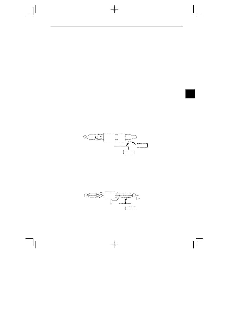
Installing a Noise Filter on Output Side
Connect a noise filter to the output side of the Inverter to reduce radio noise and inductive noise.
Induc-
tive
noise
Signal
line
Controller
Radio noise
AM radio
Power
supply
MCCB
Noise
filter
VS-626MC
5
IM
Inductive Noise:
Electromagnetic induction generates noise on the signal line, causing the control-
ler to malfunction.
Radio Noise:
Electromagnetic waves from the Inverter and cables cause the broadcasting radio
receiver to make noise.
Fig
3.10
Installing a Noise Filter on the Output Side
Countermeasures Against Inductive Noise
As described previously, a noise filter can be used to prevent inductive noise from being generated on the
output side. Alternatively, cables can be routed through a grounded metal pipe to prevent inductive noise.
Keeping the metal pipe at least 30 cm away from the signal line considerably reduces inductive noise.
IM
Signal line
Controller
Metal pipe
30 cm min.
Power
supply
MCCB
VS-626MC
5
Fig
3.11
Countermeasures Against Inductive Noise
3