Yaskawa VS-626 MC5 User Manual
Page 42
3.4
Wiring Main Circuit Terminals
- 9
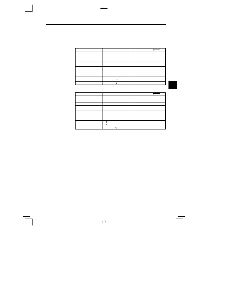
3.4.2 Main Circuit Terminal Functions
Main circuit terminal functions are summarized according to terminal symbols in Table 3.4 and Table 3.5.
Wire the terminals correctly for the desired purposes.
Table
3.4
200 V Class Main Circuit Terminal Functions
Purpose
Terminal Symbol
Model
: CIMR
-MC5
A
Main circuit power input
R (L1), S (L2), T (L3)
20P4 to 2075
Inverter outputs
U (T1), V (T2), W (T3)
20P4 to 2075 (all models)
DC power input
¨ 1 -- ©
20P4 to 2022
Braking Resistor Unit connec-
tion
B1, B2
20P4 to 27P5
DC reactor connection
¨ 1 -- ¨ 2
20P4 to 2015
Braking Unit connection
¨ 3 -- ©
2011 to 2075
Cooling fan power input
r,
2018 to 2022
Cooling fan power input
control power input)
r,
2030 to 2075
Ground
20P4 to 2075 (all models)
Note Models CIMR-MC5A2030 to 2075 do not support standard DC power input.
Table
3.5
400 V Class Main Circuit Terminal Functions
Purpose
Terminal Symbol
Model
: CIMR
-MC5
A
Main circuit power input
R (L1), S (L2), T (L3)
40P4 to 4075
Inverter outputs
U (T1), V (T2), W (T3)
40P4 to 4075 (all models)
DC power input
¨ 1 -- ©
40P4 to 4045
Braking Resistor Unit connec-
tion
B1, B2
40P4 to 4015
DC reactor connection
¨ 1 -- ¨ 2
40P4 to 4015
Braking Unit connection
¨ 3 -- ©
4018 to 4075
Cooling fan power input
r,
4018 to 4045
Cooling fan power input
(control power input)
r -- 200: 200 to 230 VAC input
r -- 400: 380 to 460 VAC input
4055 to 4075
Ground
40P4 to 4075 (all models)
Note Models CIMR-MC5A4055 to 4075 do not support standard DC power input.
3