Yaskawa VS-626 MC5 User Manual
Page 134
6.3
Flux Vector Control
- 31
D
If a fault occurred during autotuing, refer to 6.3.5 Autotuning Faults for details on correcting the cause
of the fault and perform autotuning again.
D
After autotuning of Motor 1 is completed, perform autotuning of Motor 2 using the same procedures.
J
Adjustment after autotuning
1.
Adjust the following constants when autotuning has completed.
x
Max. frequency (E1-04) : No-load frequency at the maximum speed (Hz)
x
Max. voltage (E1-05) = No-load voltage at maximum speed (V)
2.
Adjust the ASR gain (C5-01, C5-03) within the range below.
(C5-01C5-03) = Factory setting (20.00)
factory setting
Max. Speed/ base speed
6.3.5 Autotuning Faults
D
One of the fault messages in the following table will be displayed if a fault occurs during autotuning
and the motor will stop. In this case, determine the cause of the fault, correct it, and perform autotuning
again.
D
The fault display can be cleared by pressing the MENU Key.
D
The motor constants will revert to their default settings if a fault occurs. Set these constants again be-
fore starting autotuning again.
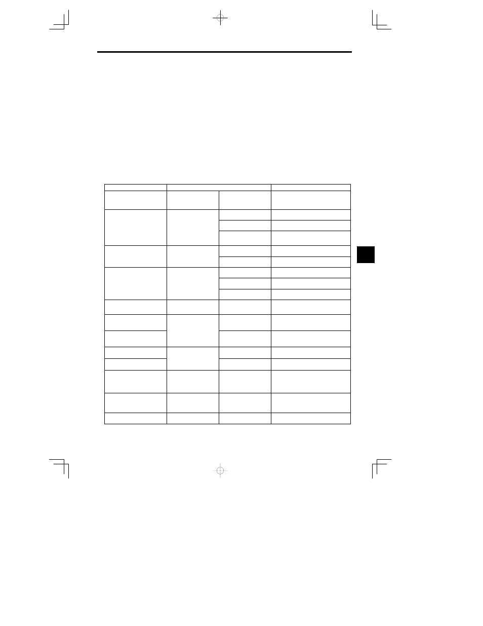
Table
6.3
Troubleshooting Autotuning Faults for Flux Vector Control
Fault Display
Probable Cause
Remedy
Data Invalid
(Motor data fault)
There was a fault in the data
set during autotuning.
There was a fault in the rela-
tionship between the rated
frequency, rated speed, and
number of poles.
Change the settings to conform to the follow-
ing equation:
Rated speed < 120
u Motor frequency/Num-
ber of poles
A load is connected to the
motor shaft.
Remove the load.
ALARM: Over Load
(Excessive tuning load)
The effective load factor ex-
ceeded 20% during autotun-
i
There was a setting fault dur-
ing autotuning.
Check the rated current setting. Change if
necessary.
(Excessive tuning load)
g
ing.
There is a motor bearing
problem.
Turn the Inverter off and rotate the motor by
hand.
Replace the motor if it doesn’t turn smoothly.
Motor speed
The torque reference value
exceeded 100% during auto
There is a broken/discon-
nected motor power wire.
Check and replace wiring components if nec-
essary.
Motor speed
(Motor speed fault)
exceeded 100% during auto-
tuning.
A load is connected to the
motor shaft.
Remove the load.
The torque limit function is
operating.
Initialize the torque limit constants (H7-01 to
H7-04).
Accelerate
(Acceleration fault)
The motor doesn’t accelerate
within the prescribed time.
The acceleration time is too
short.
Increase acceleration time 1 (C1-01).
(Acceleration fault)
p
A load is connected to the
motor shaft.
Remove the load.
Rated Slip
(Rated slip fault)
The rated slip setting can’t
be tuned within the pre-
scribed time.
A load is connected to the
motor shaft.
Remove the load.
Saturation -1
(Iron core saturation coefficient
1 fault)
The core-saturation coeffi-
cients can’t be tuned within
The rated current setting isn’t
correct.
Check and change the setting if necessary.
Saturation -2
(Iron core saturation coefficient
2 fault)
cients can’t be tuned within
the prescribed time.
There is a broken/discon-
nected motor power wire.
Check and replace wiring components if nec-
essary.
Resistance
(Line-to-line resistance fault)
The motor terminal resist-
ance or no-load current set-
The rated current setting isn’t
correct.
Check and change the setting if necessary.
No-load Current
(No-load current fault)
ance or no-load current set-
ting can’t be tuned within the
prescribed time.
There is a broken/discon-
nected motor power wire.
Check and replace wiring components if nec-
essary.
Motor Direction Fault
Motor direction fault
There is a faulty connection
between the Inverter and PC
(A or B phase) or the Invert-
er and Motor (U, V, or W
phase).
S Check the PG wiring.
S Check the motor wiring.
S Check the PG rotation direction and
constant F1-05.
PG Circuit Fault
PGO: PG break detected)
Pulses aren’t being input
from the PG even though a
rotation output is being sent
to the motor.
S The cable to the PG is bro-
ken/disconnected.
S The PG’s power supply is
broken/disconnected.
Check the wiring and correct any problems.
Tune Aborted
Minor Fault:
A minor Inverter fault oc-
curred.
Check the minor fault indicated in the boxes
in the display shown at the left.
6