Yaskawa VS-626 MC5 User Manual
Page 181
7.3
Common Functions
- 43
During Run (Setting: 0)
OFF
The run command is OFF and there is not output voltage.
ON
The run command is ON or a voltage is being output.
During Run 2 (Setting: 37)
OFF
The Inverter is not outputting a frequency. (Baseblock, DC injection braking, initial excitation,
or stopped)
ON
The Inverter is outputting a frequency.
D
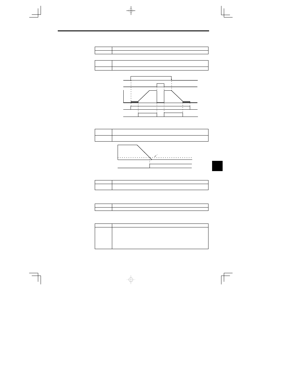
These outputs can be used to indicate the Inverter’s operating status.
Run command
Baseblock command
Output frequency
ON
ON
OFF
OFF
ON
OFF
ON
OFF
During run 1 output
During run 2 output
Fig
7.26
Timing Chart for “During RUN” Output
Zero-speed (Setting: 1)
OFF
The output frequency is greater than the minimum output frequency (E1-09).
(With flux vector control, motor speed is greater than the zero speed level (b2-01).)
ON
The output frequency is less than the minimum output frequency (E1-09).
(With flux vector control, motor speed is less than the zero speed level (b2-01).)
Output frequency
(Motor speed)
Minimum output frequency (E1-09)
(Zero speed level (b2-01) when flux vector control is
being used.)
Zero-speed output
OFF
ON
Fig
7.27
Timing Chart for Zero-speed
Motor Overload (OL1) Pre-alarm (Setting: 1F)
OFF
The motor protection function’s electronic thermal value is less than 90% of the detection level.
ON
The motor protection function’s electronic thermal value is greater than 90% of the detection
level.
D
This output function is valid when the motor overload protection function is enabled (L1-01 =1).
D
This output can be used to warn of overheating before the protection function itself operates.
Inverter Overheat (OH) Pre-alarm (Setting: 20)
OFF
The cooling fin temperature is less than the “OH Pre-Alarm Level” set in L8-02.
ON
The cooling fin temperature exceeds the “OH Pre-Alarm Level” set in L8-02.
D
This output function indicates that the temperature of the cooling fins reaches the temperature set in
L8-02 (the Inverter overheating alarm detection level).
Speed reference limit (Setting: 31)
OFF
Other than ON condition
ON
Enables the speed reference limit in the following conditions (During flux vector control mode):
1. Frequency reference
Frequency reference upper limit (d2--01)
Frequency reference
Frequency reference lower limit (d2--02)
Frequency reference
Output frequency lower limit of the multi--function analog input
(Setting: 9)
2. The frequency reference is less than the Min. output frequency (E1--09), and b1--05 is set to
1, 2, ot 5.
7