Yaskawa VS-626 MC5 User Manual
Page 151
7.2
Flux Vector Control
- 13
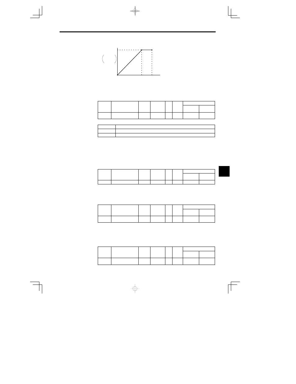
Frequency
(
Hz
)
Output voltage
(
V
)
VMAX
(
E1-05
)
FMIN
(
E1-09
)
FA
(
E1-06
)
FMAX
(
E1-04
)
V BASE
(
E1-13
)
Fig
7.7
V/f Pattern Adjustment
Units for V/f Pattern Settings: o1-04
The units used for V/f pattern frequency settings can be changed when flux vector control has been se-
lected.
User
Change
during
Setting
Factory
Valid Access Levels
User
Constant
Number
Name
during
Opera-
tion
Setting
Range
Unit
Factory
Setting
Open Loop
Vector
Flux Vector
o1-04
Frequency units of
constant setting
0 1
--
0
B
D
Display Unit Settings
Setting
Function
0
Units: Hz
1
Units: r/min
D
The setting units for constants E1-04, E1-06, and E1-09 can be changed.
D
The unit for other frequencies will not change.
D
Constant o1-04 is specific to flux vector control.
J
Setting Motor Constants: E2-01 to E2-09
The motor constants (function E2) will all be set automatically when autotuning is performed.
Set these constants manually if autotuning can’t be completed properly.
Motor Rated Current: E2-01
User
Change
during
Setting
Factory
Valid Access Levels
User
Constant
Number
Name
during
Opera-
tion
Setting
Range
Unit
Factory
Setting
Open Loop
Vector
Flux Vector
E2-01
Motor rated current
0.32 to 6.40
A
1.90
Q
Q
D
The setting range is 10% to 200% of the Inverter rated output current. The default setting depends upon
the Inverter capacity. (The table shows the default setting for 200 V class, 0.4 kW Inverters.) See page
NO TAG.)
D
Set the rated current (A) shown on the motor nameplate.
Motor Rated Slip: E2-02
User
Change
during
Setting
Factory
Valid Access Levels
User
Constant
Number
Name
during
Opera-
tion
Setting
Range
Unit
Factory
Setting
Open Loop
Vector
Flux Vector
E2-02
Motor rated slip
0.00 to
20.00
Hz
2.90
Q
Q
D
The default setting depends upon the Inverter capacity.
(The table shows the default settings for 200 V class, 0.4 kW Inverters.) (See page NO TAG.)
D
Calculate the rated slip (E2-02) from the value shown on the motor nameplate with the following equa-
tion and set this value.
Rated slip = rated frequency (Hz) -- rated speed (r/min)
u number of poles/120
Motor No-load Current: E2-03
User
Change
during
Setting
Factory
Valid Access Levels
User
Constant
Number
Name
during
Opera-
tion
Setting
Range
Unit
Factory
Setting
Open Loop
Vector
Flux Vector
E2-03
Motor no-load current
0.00 to
1500.0
A
1.20
Q
Q
7