2 nomenclature – Yaskawa VS-626 MC5 User Manual
Page 22
Advertising
Introduction
1.2.1 VS-626MC5 Components
- 6
1.2
Nomenclature
This section provides the names of VS-626MC5 components, and the components and functions of the Digital
Operator.
1.2.1 VS-626MC5 Components
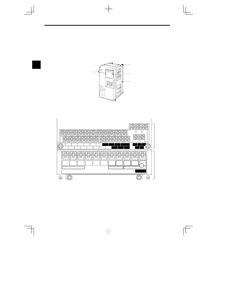
The appearance of Inverter and the names of its components are shown in Figure 1.2.
626 MC5
Mounting hole
Protective cover (top)
Digital Operator
JVOP-130
Front cover
Die-cast case
Protective cover (bottom)
Fig
1.2
Appearance of VS-626MC5, Model CIMR-MC5A20P4 (200 V, 0.4 kW)
A 200 V Class Inverter with 0.4 kW Output is shown below with the front cover removed.
Control circuit
terminals
Main circuit
terminals
10
B2
V
T2
Power input
Braking Resistor
Motor output
CHARGE
1
2
3
4
5
6
7
8
21
22
23
9
11 12
(
G
)
13
14
15
16
17
25
26
27
33
18
19
20
R
L1
S
L2
T
L3
©
¨
1
¨
2
B1
W/T3
U
T1
Fig
1.3
Terminal Arrangement
1
Advertising