Yaskawa VS-626 MC5 User Manual
Page 149
7.2
Flux Vector Control
- 11
7.2.1 Torque Limit Function
With flux vector control, the torque limit can be applied at an arbitrary value because the torque output
by the motor is calculated internally.
The torque limit function is useful when the load cannot sustain a torque above a certain level or regenera-
tive torque above a certain level.
The two ways to apply a torque limit are listed below.
D
Setting torque limits with the constants
D
Limiting torque with the analog inputs
The lower torque limit will be used if both of these methods are set. The accuracy of the torque limit is
r5% at all frequencies.
J
Setting a Torque Limit with Constants: L7-01 to L7-04
D
Torque limits can be set separately for the 4 ways that torque can be applied: forward torque, reverse
torque, forward regenerative torque, and reverse forward regenerative torque.
User
Change
during
Setting
Factory
Valid Access Levels
User
Constant
Number
Name
during
Opera-
tion
Setting
Range
Unit
Factory
Setting
Open Loop
Vector
Flux Vector
L7-01
Forward torque limit
0 to 300
%
200
B
B
L7-02
Reverse torque limit
0 to 300
%
200
B
B
L7-03
Forward regenerative
torque limit
0 to 300
%
200
B
B
L7-04
Reverse regenerative
torque limit
0 to 300
%
200
B
B
D
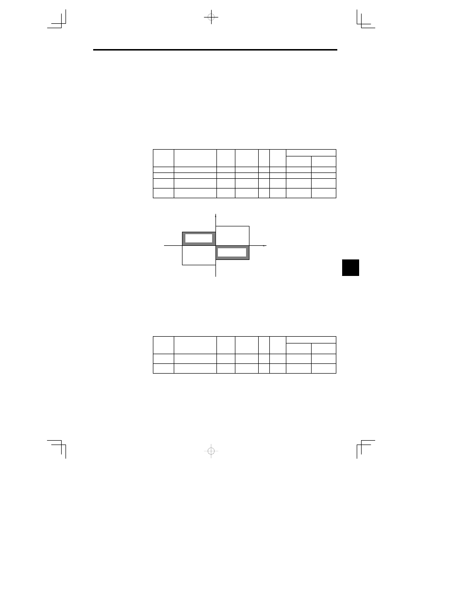
Figure 7.5 shows the relationship between each constant and the output torque.
L7-04
L7-01
L7-02
L7-03
Output torque
Forward
direction
Reverse
direction
Motor speed
Reverse
Forward
Regenerative
torque
Regenerative
torque
Fig
7.5
Torque Limit Function
D
When the torque limit function is used, the torque control has priority and motor speed control and
compensation will be disregarded, so the acceleration/deceleration times might be lengthened and mo-
tor speed might be reduced.
J
Limiting Torque with Analog Inputs: H3-05, H3-09
The following two analog inputs that can be used to limit torque. Use either or both of these inputs as need-
ed with constants H3-05 and H3-09.
D
Multi-function analog input terminal 16
D
Frequency reference (current) terminal 14
User
Change
during
Setting
Factory
Valid Access Levels
User
Constant
Number
Name
during
Opera-
tion
Setting
Range
Unit
Factory
Setting
Open Loop
Vector
Flux Vector
H3-05
Multi-function analog
input (terminal 16)
0 to 1F
--
0
B
B
H3-09
Multi-function analog
input (terminal 14)
1 to 1F
--
1F
A
A
7