Yaskawa VS-626 MC5 User Manual
Page 168
Advanced Operation
7.3.4 Option Constants: F
- 30
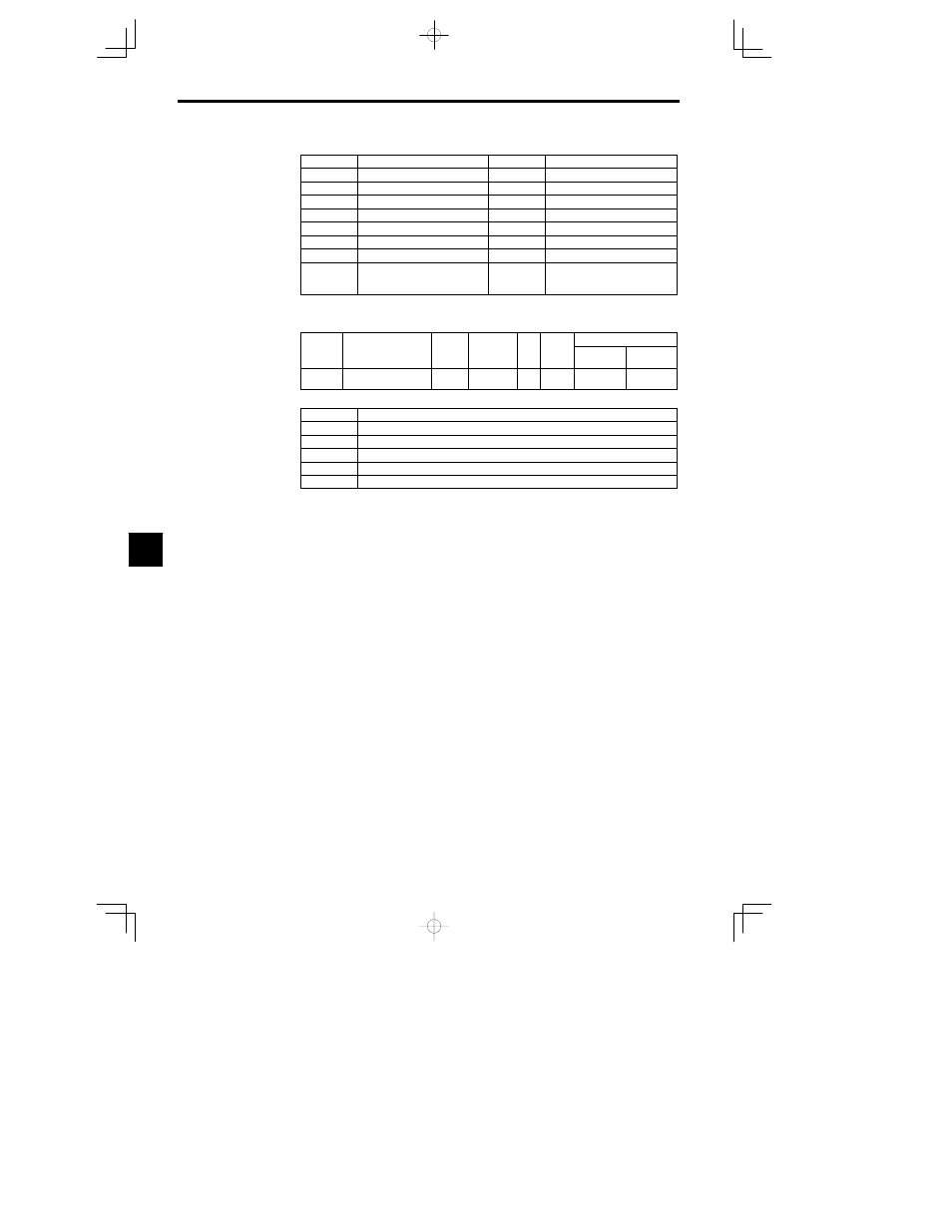
Coded Outputs
Bit 3210
Meaning
Bit 3210
Meaning
0000
No fault
1000
External fault EF
0001
Overcurrent SC OC GF
1001
Controller fault CPF
0010
Overvoltage OV
1010
Motor overload OL1
0011
Inverter overload OL2
1011
Not used
0100
Inverter overheat OH OH1
1100
Power loss UV1 UV2 UV3
0101
Overspeed OS
1101
Excessive speed deviation DEV
0110
Fuse blown PUF
1110
PG disconnected PGO
0111
Braking Resistor Unit over-
heat RH
Braking Transistor fault RR
1111
Not used.
J
Pulse Monitor Card: F7-01
D
When using a PO-36F Pulse Monitor Card, set the output pulse in constant F7-01.
User
Change
during
Setting
Factory
Valid Access Levels
User
Constant
Number
Name
during
Opera-
tion
Setting
Range
Unit
Factory
Setting
Open Loop
Vector
Flux Vector
F7-01
Frequency multiple
selection
0 to 4
--
1
B
B
D
Settings
Setting
Description
0
1F
1 x Inverter output frequency
1
6F
6 x Inverter output frequency
2
10F
10 x Inverter output frequency
3
12F
12 x Inverter output frequency
4
36F
36 x Inverter output frequency
D
“F” indicates the output frequency (Hz). For example, if “0” (1F) is set, when the output frequency
is 60 Hz there will be an output of 60 pulses per second. (Duty 50%)
7