Yaskawa VS-626 MC5 User Manual
Page 287
Appendix
- 18
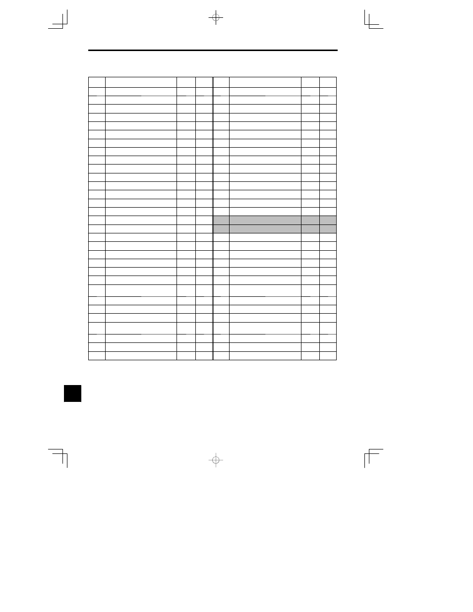
Table 12.1
User Constants (Continued)
No.
Name
(Display)
Factory
Setting
Setting
No.
Name
(Display)
Factory
Setting
Setting
H4-04
Monitor selection (terminal 23)
(Terminal 23 Sel)
18
L6-02
Torque detection level 1
(Torq Det 1 Lvl)
150
H4-05
Gain (terminal 23)
(Terminal 23 Gain)
0.50
L6-03
Torque detection time 1
(Torq Det 1 Time)
0.1
H4-06
Bias (terminal 23)
(Terminal 23 Bias)
0.0
L6-04
Torque detection selection 2
(Torq Det 2 Lvl)
0
H4-07
Analog output signal level selection
(AO Level Select)
0
L6-05
Torque detection level 2
(Torq Det 2 Lvl)
150
H5-01
Station address
(Serial Comm Adr)
1F
L6-06
Torque detection time 2
(Torq Det 2 time)
0.1
H5-02
Communication speed selection
(Serial Baud Rate)
3
L7-01
Forward torque limit
(Torq Limit Fwd)
200
H5-03
Communication parity selection
(Serial Com Sel)
0
L7-02
Reverse torque limit
(Torq Limit Rev)
200
H5-04
Stopping method after communication error
(Serial Fault Sel)
3
L7-03
Forward regenerative torque limit
(Torq Lmt Fwd Rgn)
200
H5-05
Communication error detection selection
1
(Serial Flt Dtct)
1
L7-04
Reverse regenerative torque limit
(Torq Lmt Rev Rgn)
200
L1-01
Motor protection selection
(MOL Fault Select)
1
L8-01
Protect selection for internal DB resistor
(DB Resistor Prot)
0
L1-02
Motor protection time constant
(MOL Time Const)
1.0
L8-02
Overheat pre-alarm level
(OH Pre-Alarm Lvl)
95
L2-01
Momentary power loss detection
(PwrL Selection)
0
L8-03
Operation selection after overheat pre-alarm
(OH Pre-Alarm Sel)
3
L2-02
Momentary power loss ridethru time
(PwrL Ridethru t)
0.7
2
L8-05
Input open-phase protection selection
(Ph Loss In Sel)
0
L2-03
Min. baseblock time
(PwrL Baseblock t)
0.5
2
L8-07
Output open-phase protection selection
(Ph Loss Out Sel)
0
L2-04
Voltage recovery time
(PwrL V/F Ramp t)
0.3
2
L8--10
Ground protection selection
(GND Det Sel)
1
L2-05
Undervoltage detection level
(PUV Det Level)
190
3
L8--17
Carrier frequency reduction selection
(L--Spd 1GBT Prict)
1
L2-06
KEB deceleration rate
(KEB Frequency)
0.0
L8--19
OL2 characteristics selection for low speeds
(OL2 Chara @ L--Spd)
0
L3-01
Stall prevention selection during accel
(StallP Accel Sel)
1
o1-01
Monitor selection
(Monitor Select)
6
L3-02
Stall prevention level during accel
(StallP Accel Lvl)
150
o1-02
Monitor selection after power up
(Power-On Monitor)
1
L3-03
Stall prevention limit during accel
(StallP CHP Lvl)
50
o1-03
Frequency units of reference setting/monitor
(Display Scaling)
0
L3-04
Stall prevention selection during decel
(StallP Decel Sel)
1
o1-04
Frequency units of constant setting
(Display Units)
0
L3-05
Stall prevention selection during running
(StallP Run Sel)
1
o1-05
Constant no. display selection
(Address Display)
0
L3-06
Stall prevention level during running
(StallP Run Level)
160
o2-01
LOCAL/REMOTE key enable/disable
(Local/Remote Key)
1
L4-01
Speed agree detection level
(Spd Agree Level)
0.0
o2-02
STOP key during control circuit terminal op-
eration
(Oper STOP Key)
1
L4-02
Speed agree detection width
(Spd Agree Width)
2.0
o2-03
User constant initial value
(User Defaults)
0
L4-03
Speed agree detection level (+/--)
(Spd Agree Lvl + --)
0.0
o2-04
kVA selection
(Inverter Model #)
0
2
L4-04
Speed agree detection width (+/--)
(Spd Agree Wdth + --)
2.0
o2-05
Frequency reference setting method
1
(Operator M.O.P.)
0
L4-05
Operation when frequency reference is missing
(Ref Loss Sel)
0
o2-06
Operation selection when digital operator is
disconnected
(Oper Detection)
0
L5-01
Number of auto restart attempts
(Num of Restarts)
0
o2-07
Cumulative operation time setting
(Elapsed Time Set)
L5-02
Auto restart operation selection
(Restart Sel)
0
o2-08
Cumulative operation time selection
(Elapsed Time Run)
0
L6-01
Torque detection selection 1
(Torq Det 1 Sel)
0
o2-09
Initialize mode selection
1
(Init Mode Sel)
0
4
* 1. Not displayed for some models depending on software version No.
* 2. Setting unit and initial setting depend on Inverter capacity.
* 3. Setting for 200 V class Inverters. For 400 V class Inverters, double the value.
* 4. Not initialized. (Japanese standard specification is o2-09 = 0.)
12