Yaskawa VS-626 MC5 User Manual
Page 119
Basic Operation
6.1.8 Multi-function Input Settings: H1-01 through H1-06
- 16
J
Acceleration/Deceleration Time Selectors 1 and 2: “7” and “1A”
D
Four acceleration times and four deceleration times can be set. The multi-function inputs can be set
as acceleration/deceleration time selectors 1 and 2 to switch between these acceleration and decelera-
tion times.
Setting
Function
7
Acceleration/Deceleration time selector 1
1A
Acceleration/Deceleration time selector 2
D
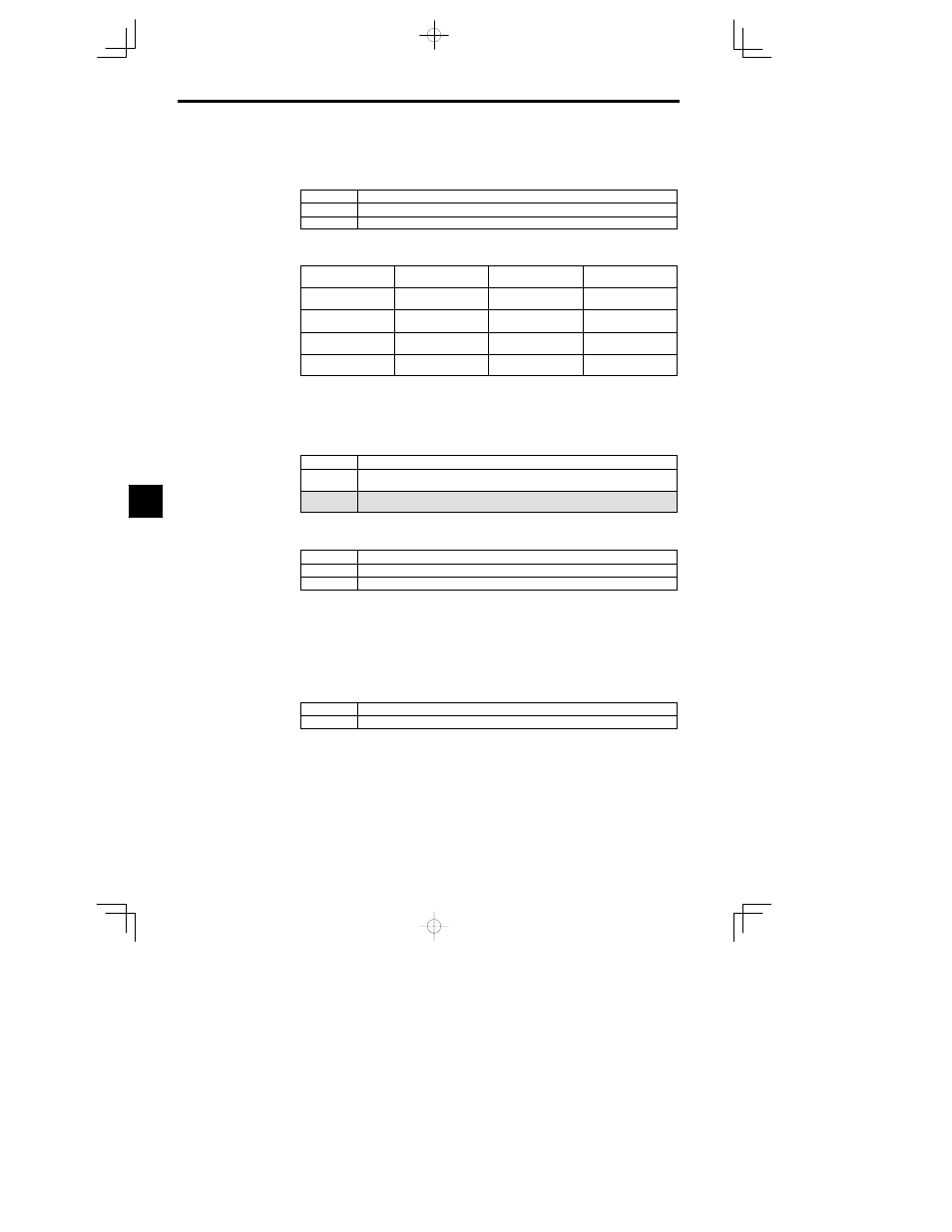
The following table shows which acceleration and deceleration times are selected by each possible
combination of acceleration/deceleration time selectors 1 and 2. The acceleration and deceleration
times can be changed while the Inverter is operating.
Accel/Decel Time Se-
lector 1
Accel/Decel Time Se-
lector 2
Acceleration Time
Deceleration Time
OFF or not set
OFF or not set
Acceleration time 1
(C1-01)
Deceleration time 1
(C1-02)
ON
OFF or not set
Acceleration time 2
(C1-03)
Deceleration time 2
(C1-04)
OFF or not set
ON
Acceleration time 3
(C1-05)
Deceleration time 3
(C1-06)
ON
ON
Acceleration time 4
(C1-07)
Deceleration time 4
(C1-08)
J
Emergency Stop: “15” “17”
D
When the multi-function input that is set as an emergency stop is turned ON, the motor will decelerate
to a stop at the rate set with the deceleration time in C1-09 (emergency stop time).
D
To clear the emergency stop, turn OFF the run command, turn OFF the emergency stop input, and then
turn ON the run command again.
D
Set “17” to make the emergency stop the normally closed condition.
Setting
Function
15
Emergency stop (normally open condition: Decelerates to stop when ON in the emergency stop
period C1--09)
17
Emergency stop (normally closed condition: Decelerates to stop when OFF in the emergency
stop period C1--09)
J
Forward and Reverse Jog Commands: “12” and “13”
The jogging can be performed in forward or reverse.
Setting
Function
12
Forward jog command: Runs forward at the jog frequency (d1-09).
13
Reverse jog command: Runs in reverse at the jog frequency (d1-09).
D
The forward jog and reverse jog commands have priority over other frequency reference commands.
D
The inverter will stop operation with the stopping method set in b1-03 if the forward jog and reverse
jog commands are both ON for more than 500 ms.
D
Turn ON either the forward jog command or the reverse jog command, not both.
D
These jog commands can operate the Inverter independently. It isn’t necessary for a forward/reverse
run command to be input.
J
Terminal 13/14 Switch: “1F”
D
When this function is set for a multi-function input, that input terminal can be used to switch between
terminal 13 and terminal 14.
OFF
The analog input from terminal 13 is used as the master-speed frequency reference.
ON
The analog input from terminal 14 is used as the master speed frequency reference.
D
When terminal 14 is used as the frequency reference, set “1F” (frequency reference) in constant H3-09;
this constant is the function selector for frequency reference (current) terminal 14. A setting fault
(OPE03) will occur if this function is selected without setting “1F” in H3-09.
D
When H3-09 is set to “1F” (frequency reference) but none of the multi-function inputs is set to “1F”
(terminal 13/14 switch), the sum of the inputs from terminals 13 and 14 will be used as the master-
speed frequency reference.
6