Yaskawa VS-626 MC5 User Manual
Page 203
7.4
Optional Functions
- 65
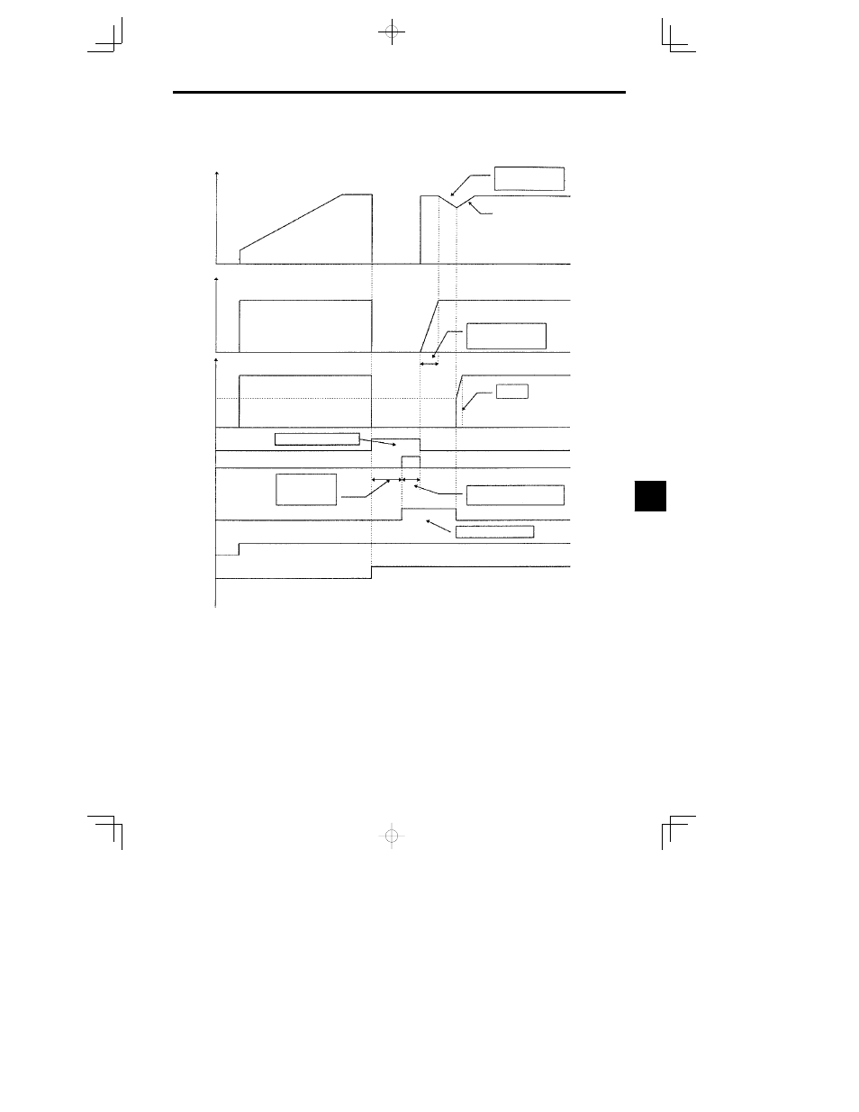
Fig 7.36 shows motor constant change sequence during winding change.
Speed Search
Deceleration TIme
b3-03
2nd motor
constant
calculation time
Note When the flux vector control mode is selected, the torque
reference increases from zero within 64msec.
(For open loop vector mode, torque reference increases
50% of the torque limit. )
Hz
Fout
V
0
Output Voltage
Torque Limit
50%
0%
Total base block me
RUN Commatd
Motor 1
Motor 2
The ramp time is
dependent on the
accek timesetting.
Voltage recovety time
L2--04.
64 ms
Minimum base block time
L2--03
During speed search
Fig
7.36
Winding Change Sequence
D
When selecting a motor for winding change application with a MC5 drive, it is necessary to check the
base and maximum frequencies, no-load voltage at base and maximum frequencies, leak inductance,
full load rated current, etc. for both Y- and -windings.
D
Heavy cutting during winding change may cause the winding change to malfunction and/or stall the
system.
7